Understanding Memory Architecture: A Detailed Guide to Caches and Locality in Computing
500 likes | 625 Vues
This guide delves into computer memory architecture, visualized as a stack of "pigeon holes," and explains how memory is organized, addressed, and accessed. It covers essential concepts such as addressing bits, memory hierarchy, and the importance of locality—both spatial and temporal. Furthermore, it illustrates the roll of caches in improving access times through an analysis of average memory access time (AMAT) and cost comparisons between DRAM and SRAM. This comprehensive overview equips readers with the foundational knowledge necessary for understanding more complex computing topics.

Understanding Memory Architecture: A Detailed Guide to Caches and Locality in Computing
E N D
Presentation Transcript
CS1104 Help Session IMemorySemester II 2001/02 Colin Tan, S15-04-05, Ctank@comp.nus.edu.sg
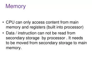
Memory • Memory can be visualized as a stack of pigeon holes. Current computers have about 128,000,000 pigeon holes. • Each pigeon hole is given a number, starting from 0. This number is called an “address”. • Each pigeon hole will contain either data (e.g. numbers you want to add together) or instruction (e.g. add two numbers)
Memory • Memory locations 0 to 3 contain instructions, locations 4 to 6 contain data. • Note: In reality, instructions are also encoded into numbers!
Addresses • As mentioned, each pigeon hole has a number identifying it called an “address”. • When the CPU requires an instruction, it will send the instruction’s “address” to memory, and the memory will return the instruction at that address. • E.g. At IF CPU will send “0” to memory, and the memory returns li t1, 5 • At MEM CPU will send “6” to memory, and memory returns “10”. • At WB, CPU writes “10” back to t1.
Addressing Bits • Computers work only in binary • Hence addresses generated in the previous example are also in binary! • In general, to address a maximum of n memory locations, you will need m = log2 n bits in your address. • Conversely, if you had m bits in your address, you can access a maximum of 2mmemory locations.
Memory Hierarchy • Motivation • Not all memory is created equal • Cheap Memory => Slow • Fast Memory => Expensive • DRAM, 70 ns access time, $1/MByte • SRAM, 8 ns access time, $50/Mbyte • So, you can choose either: • Have fast but very small memory, OR • Large but very slow memory.
Memory Hierarchy • Memory hierarchy gives you a third option: • Large, but very fast memory • Though slower than the expensive memory mentioned earlier.
Locality • “Locality” is a particular type of behavior exhibited by running programs: • Spatial locality: If a memory location has been accessed, it is very likely its neighbor will also be accessed. • Temporal locality: If a memory location has been accessed, it is very likely that it will be accessed again sometime soon.
Locality - Example • Consider the following program: for(i=0; i<10; i++) a[i] = b[i] + c[i];
Locality - Example • In memory it will look like this:
Locality - Example • Tracing the execution of the program:
Locality - Example • Focusing only on the addresses of the fetched instructions, we see that the addresses the instructions are fetched from are: 0, 1, 2, 3, 4, 5, 6, 7, 8, 9, 10, 2, 3, 4, 5, 6, 7, 8, 9, 10, 2, 3, 4, 5, … • Here we see both: • Spatial locality (e.g. after location 0 is accessed, location 1 is accessed, then 2, etc.) • Temporal locality (e.g. location 2 is accessed 10 times!)
Effect of Locality • Locality means that in the short run out of all the memory you have (perhaps up to 128,000,000 pigeon holes!), only a very small number of locations are actually being accessed! • In our example for ten iterations only memory locations 2 to 10 are being accessed out of 128,000,000 possible locations! • What if we had a tiny amount of very fast (but expensive!) memory and kept these locations in that fast memory? • We can speed up access times dramatically!! • This is the idea behind caches.
How Do Caches Help? • The average time to access memory (AMAT) is given by: • AMAT = hit_rate * Tcache + miss_rate x (Tmemory + Tcache) • Tcache = Time to read the cache (8ns for SRAM cache) • Tmemory = Time to read main memory (70ns for DRAM) • miss_rate = Probability of not finding what we want in the cache. • Because of locality, miss_rate is very small • Typically about 3% to 5%. • Here, our AMAT = 0.95 * 8ns + 0.05 x (70 + 8) ns = 11.5 ns • Our AMAT is about 43% slower than pure SRAM cache memory (11.5 ns vs. 8 ns)
How Do Caches Help? • What about cost? • Let’s consider: • A system with 32 MB of DRAM memory, 512KB of SRAM cache. • Cost is $1/MB for DRAM, and $50/MB for SRAM. • If we had 32MB of SRAM, access time is 8 ns, but cost will be $1,600 • With 32MB of DRAM, cost is $32, but access time is 70 ns! • But with 32MB of DRAM and 512 (1/2 MB) of SRAM, cost will be: $32 + (512/1024) * 50 = $57!
How do Caches Help? • So with pure SRAM, we can have 8 ms average access time at $1,600. • With pure DRAM, our memory will cost $32, but all accesses will take 70 ns! • With DRAM memory and SRAM cache, we can have 11.5 ms access time at $57. • So for a performance drop of 43%, we have a cost savings of >2700%! • Hence caches give us large memory size (32 MB), at close to the cost of the DRAM technology ($57 vs. $32), but at close to the speed of expensive SRAM technology (11.5 ms vs. 8 ms)
Block Cache Architecture • Caches consist of blocks (or lines). Each block stores data from memory: • Block allocation problem: • Given data from an address A, how do we decide which block of cache its data should go to?
The Block Allocation Problem • 3 possible solutions: • Data from each address A will go to to a fixed block. • Direct Mapped Cache • Data from each address A will go to any block. • Fully associative cache • Data from address A will go to a fix set of blocks. • Data may be put into any block within a set. • Set associative cache.
Direct Mapped Caches • The value of a portion of memory address is used to decide which block to send the data to: Address A Tag Block Index Block Offset Byte Offset • The Block Index portion is used to decide which block data from this address should go to.
Example • The number of bits in the block index is log2N, where N is the total number of blocks. • For a 4-block cache, the block index portion of the address will be 2 bits, and these 2 bits can take on the value of 00, 01, 10 or 11. • The exact value of these 2 bits will determine which block the data for that address will go to.
Direct Mapped Addressing E.g. • Show how an addresses generated by the MIPS CPU will be divided into byte offset, block offset, block index and tag portions for the following cases: i) Block size: 1 word, 128 blocks ii) Block size: 4 words, 64 blocks • All MIPS addresses are 32 bit byte addresses (i.e. they address individual bytes in a word).
Cache 00 01 10 11 Example • The value of the two block index bits will determine which block the data will go to, following the scheme shown below:
Solving Direct-Mapped Cache Problems • Question 7.7 • Basic formula: • Blk_Addr = floor(word_address/words_per_block) mod N • N here is the total number of blocks in the cache • This is the mathematical version of taking the value of the Block Index bits from the address.
A Complication:Multiple Word Blocks • Single word blocks do not support spatial locality • Spatial locality: Likelihood of accessing neighbor of a piece of data that was just accessed is high. • But with single word blocks, none of the neighbors are in cache! • All accesses to neighbors that were not accessed before will miss!
Tag Block Index Block Offset Byte Offset Accessing Individual Words • In our example, each block has 4 words. • But we always access memory 1 word at a time! (e.g. lw) • Use the Block Offset to specify which of the 4 words in a block we want to read: Address A
The Block Offset • Number of block offset bits = log2M, where M is the number of words per block. • For our example, M=4. So number of block offset bits is 2. • These two bits can take on the values of 00, 01, 10 and 11. • Note that for single word blocks, the number of block offset bits is log2 1, which is 0. I.e. There are no block offset bits for single-word blocks. • These values determine exactly which word within a block address A is referring to:
01000 00010010 00000000 00 01010 00010010 00000000 00 11011 00010010 00000000 00 Who am I?Purpose of the Tag • Many different addresses may map to the same block: e.g. (Block Index portions shown highlighted) • All 3 addresses are different, but all map to block 00010010
Disambiguation • We need a way to disambiguate the situation • Otherwise how do we know that the data in block x actually comes from address A and not from another address A’ that has the same block index bit value? • The portion of the address A to the left of the Block Index can be used for disambiguation. • This portion is called the tag, and the tag for address A is stored in the cache together with address A data.
Tag Word 00 Word 01 Word 10 Word 11 00 01 10 11 The Tag • When we access the cache, the Tag portion and Block Index portions of address A are extracted. • The Block Index portion will tell the cache controller which block of cache to look at. • The Tag portion is compared against the tag stored in the block. If the tags match, we have a cache hit. The data is read from the cache.
Address A Tag Block Index Block Offset Byte Offset Accessing Individual Bytes • MIPS addresses are byte addresses, and actually index individual bytes rather than words. • Each MIPS word consists of 4 bytes. • The byte offset tells us exactly which byte within a word we are referring to.
Advantages & Disadvantages ofDirect Mapped Caches • Advantages: • Simple to implement • Fast performance • Less time to detect a cache hit => less time to get data from the cache => faster performance • Disadvantages • Poor temporal locality. • Many addresses may map to the same block. • The next time address A is accessed, it may have been replaced by the contents of address A’.
Improving Temporal LocalityThe Fully Associative Cache • In the fully associative cache, data from an address A can go to any block in cache. • In practice, data will go into the first available cache block. • When the cache is full, a replacement policyis invoked to choose which block of cache to throw out.
Advantages and DisadvantagesFully Associative Cache • Good temporal locality properties • Flexible block placement allows smart replacement policies such that blocks that are likely to be referenced again will not be replaced. E.g. LRU, LFU. • Disadvantages • Complex and too expensive for large caches • Each block needs a comparator to check the tag. • With 8192 blocks, we need 8192 comparators!
A CompromiseSet Associative Caches • Represents a compromise between direct-mapped and fully associative caches. • Cache is divided into sets of blocks. • An address A is mapped directly to a set using a similar scheme as for direct mapped caches. • Once the set has been determined, the data from A may be stored in any block within a set - Fully associative within a set!
Set Associative Cache • An n-way set associative cache will have n blocks per set. • For example, for a 16-block cache that is implemented as a 2-way set associative cache, each set has 2 blocks, and we have a total of 8 sets.
Advantages and DisadvantagesSet Associative Cache • Advantages • Almost as simple to build as a direct-mapped cache. • Only n comparators are needed for an n-way set associative cache. For 2-way set-associative, only 2 comparators are needed to compare tags. • Supports temporal locality by having full associativity within a set.
Advantages and DisadvantagesSet Associative Cache • Disadvantages • Not as good as fully-associative cache in supporting temporal locality. • For LRU schemes, because of small associativity, actually possible to have 0% hit rate for temporally local data. • E.g. If our accesses are A1 A2 A3 A1 A2 A3, and if A1, A2 and A3 map to the same 2-way set, then hit rate is 0% as subsequent accesses replace previous accesses in the LRU scheme.
Multi-level Cache • Let the first level of cache (closest to CPU) be called “L1”, and the next level “L2”. • Let Phit_l1 be the hit rate of L1, Tcache_L1 be the cache access time of L1, Tmiss_L1 be the miss penalty of L1. • AMAT of L1 = Phit_l1 * Tcache_L1 + (1-Phit_l1) * Tmiss_L1 • What is Tmiss_L1? • If L1 misses, then we will attempt to get data from L2. Hence Tmiss_l1 is actually just the AMAT of L2! • Let Phit_l2 be the hit rate of L2, Tcache_l2 be the cache access time of L2, Tmiss_l2 be the miss penalty of L2.
Multilevel Cache • Tmiss_l1 = AMATl2 = Phit_l2 * Tcache_L2 + (1-Phit_l2) * Tmiss_L2 • Substitute this back and we get: AMAT of L1 = Phit_l1 * Tcache_L1 + (1-Phit_l1) * (Phit_l2 * Tcache_L2 + (1-Phit_l2) * Tmiss_L2) • Tmiss_l2 is of course the time taken to access the slow DRAM memory. • What if we had an L3 cache?
Other Problems • Question 7.9
Virtual Memory Motivation • Drive space is very very cheap • Typically about 2cents per megabyte. • It would be ideal if we could set aside a portion of drive space to be used as memory. • Unfortunately disk drives are very slow • Fastest access time is about 10ms, or about 1,000 times slower than SRAM and several hundred times slower than DRAM. • Idea: Use drive space as memory, and main memory to cache the drive space! • This is the idea behind virtual memory.
System Cache Is cached by Main Memory Is cached by Virtual Memory Main Idea • Virtual memory (residing on disk) is cached by main memory • Main memory is cached by system cache • All memory transfers are only between consecutive levels (e.g. VM to main memory, main memory to cache).
Cache vs. VM • Concept behind VM is almost identical to concept behind cache. • But different terminology! • Cache: Block VM: Page • Cache: Cache Miss VM: Page Fault • Caches implemented completely in hardware. VM implemented in software, with hardware support from CPU. • Cache speeds up main memory access, while main memory speeds up VM access.
Technical Issues of VM • Relatively cheap to remedy cache misses • Miss penalty is essentially the time taken to access the main memory (around 60-80ns). • Pipeline freezes for about 60-80 cycles. • Page Faults are EXPENSIVE! • Page fault penalty is the time taken to access the disk. • May take up to 50 or more ms, depending on the speed of the disk and I/O bus. • Wastes millions of processor cycles!
Virtual Memory Design • Because page-miss penalties are so heavy, not practical to implement direct-mapped or set-associative architectures • These have poorer hit rates. • Main memory caching of VM is always fully associative. • 1% or 2% improvement in hit rate over other fully associative or set associative designs. • But with heavy page-miss penalties, 1% improvement is A LOT! • Also relatively cheap to implement full associativity in software
Summary • Memory can be thought of as pigeon holes where CPU stores instructions and data. • Each pigeon hole (memory location) is given a number called its address. • Memory technology can be cheap and slow (DRAM) or fast and expensive (SRAM) • Locality allows us to use a small amount of fast expensive memory to store parts of the cheap and slow memory to improve performance. • Caches are organized into blocks.
Summary • Mapping between memory addresses and blocks can be accomplished by: • Directly mapping a memory location to a cache block (direct map) • Slotting a memory location to any block (fully associative) • Mapping a memory location to a set of blocks, then slotting it into any block within the set (set associative) • Virtual memory attempts to use disk space as “main memory”, DRAM main memory as cache to the disk memory, and SRAM as cache to the DRAM.