Single Stage Centrifugal Compressor Development
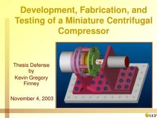
Single Stage Centrifugal Compressor Development. Kevin Finney Ray Zhou Xiaoyi Li Krishna Murty Jinying Zhu. Coupler. Motor. Compressor. March 28, 2003. Single Stage Compressor. Parts currently being manufactured by 3Dimensional Engineering in Pompano Beach


Single Stage Centrifugal Compressor Development
E N D
Presentation Transcript
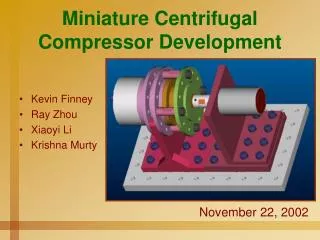
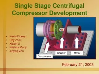
Single Stage Centrifugal Compressor Development • Kevin Finney • Ray Zhou • Xiaoyi Li • Krishna Murty • Jinying Zhu Coupler Motor Compressor March 28, 2003
Single Stage Compressor • Parts currently being manufactured by 3Dimensional Engineering in Pompano Beach • Impeller (been cast, being turned to final size) • Diffuser (on 4 axis mill now) • Inlet Guide Vane (on 4 axis mill now) • Coupler to handle 150,000 rpm is currently under study • Coupler Corporation of America is currently working on a design. • Working on own design here, using simple metal sleeves with a flexible insert to absorb misalignment
Parts being fabricated… Impeller (cast) Diffuser Inlet Guide Vane
Manufacturing of Parts • Progress of fabrication • Cast dimensions were faxed and were reviewed • All casting dimensions were oversize except one, which will not affect the performance of the compressor. • The final dimensions of the impeller, diffuser, and inlet guide vane will adhere to the iges file dimensions.
Impeller will be machined down to final dimension. Any visible voids will be spot-welded. Surface will be polished to reduce surface roughness. Diffuser and Inlet Guide Vane will be machined out of Aluminum 6061. Scallop height of 0.002”. Tolerance of Diffuser and Inlet Guide Vane will be 0.004”. Finish of Parts Will have three parts of each described above.
Impeller Inside Coupler Flow Exit Cooling Jacket Diffuser Inside Flow Inlet Motor Inside Motor Lead Wires Common Base
Warm Water Out Motor Shaft Cool Water In Cooling Jacket Design
Bearing Jig Fixtures Machined Parts ProE Model with Diffuser ProE Model with Impeller
Bearing Jig Fixtures • Designed to properly place bearing on the impeller on both the diffuser side and the top cap side. • Also press the impeller into the bearing in the diffuser without causing damage to bearing.
Future of Compressor Development • Delivery of the Impellers, Diffusers, and Inlet Guide Vanes will be March 31. • Ship Impellers to American Hoffman in West Virginia for balancing. • Assemble compressor and begin tests at low speeds to allow for break-in of bearings. • Test at maximum design speed of 150,000 revolutions per minute and collect data.