Download
1 / 12
130 likes | 414 Vues
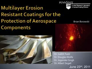
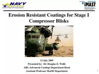
Erosion Resistant Coatings for Stage I Compressor Blisks. 13 July 2005 Presented by: Dr. Douglas E. Wolfe ARL-Advanced Coatings Department Head Assistant Professor MatSE Department. PROBLEM DESCRIPTION.

E N D
Erosion Resistant Coatings for Stage I Compressor Blisks 13 July 2005 Presented by: Dr. Douglas E. Wolfe ARL-Advanced Coatings Department Head Assistant Professor MatSE Department
PROBLEM DESCRIPTION • First Stage Compressor Blades exhibit Leading Edge (LE) curl damage associated with high angle (60o-90o) impingement of erosive media • Decreased Service Life and Increased Maintenance Costs • Expected Time of Flight ~ 5000 hrs • Realizing 2000-2500 hrs • ~100 hrs reported in aggressive environments (Iraq, Iran, Afghanistan) • 1st stage blisks ($8-10K), Airfoils ($2K) • Approximate repair cost $110,000/Engine • Major cost driver Meat-time-between-overhaul (MTBO) • Leading edge curl adversely impacts performance by: • Decreasing engine high performance between 20-30% • Increasing engine fuel consumption • Increasing engine temperature • Increasing vibrations • Decreasing serviceable life
PROBLEM DESCRIPTION * severe erosion Coated Uncoated * Uncoated Coated * Compressor blades T64 after sand-ingestion Engine Test *Technical Analysis Report No: 39/01; GE CT7-9B Turboprop Engine
EROSION PROCESS Ductile Coating Plastic Deformation and Abrasion upon impact Hard particle, i.e., sand Metallic (ductile coating) Metallic (ductile coating) Base alloy (substrate) Base alloy (substrate) Brittle Coating Cratering, subsurface cracking, and interfacial damage Hard particle, i.e., sand Coating cratering Ceramic (brittle coating) Subsurface cracking Base alloy (substrate) Base alloy (substrate)
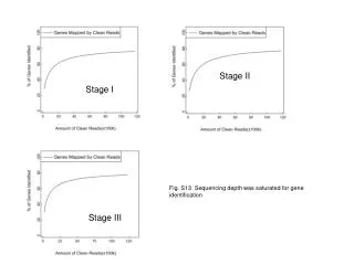
EROSION PROCESS General erosion trends as a function of impact angle For ductile (metallic) and brittle (ceramic) materials (K. Haugen et al., Wear 186-187 (1995) 179-188). Erosion rate as a function of residual stress (Cr/CrC) multilayer coatings (J.Surf.Coat.Tech 163/164 (2003)) • Erosion Resistance: • Low Angle (0o-55o) Erosion Resistance—Ceramic (hard brittle materials) • High Angle (55o-90o) Erosion Resistance—Metallic (ductile materials) • No monolithic (single layer material) provides erosion resistance (0-90o)
Hard particle, i.e., sand Base alloy (substrate) Base alloy (substrate) Multilayer Design Concept • Solution: • Combine low angle and high angle erosion resistance materials in a duplex or • or multilayer coating system design • Interlayer thickness (i.e., total number of layers, volume fraction (metallic, ceramic) • Interfacial thickness, composition, and structure • Should provide erosion resistance over wide range of impingement angles (0o-90o)
Multilayer Design Strategy Metallic (ductile) interlayer Erosion resistance at high particle impingement angles Allows build-up of thicker films/coatings Metallic ductile interlayer acts as a compliant layer absorbing energy of impacting particle preventing brittle failure Ceramic (brittle) layers Low angle erosion resistance Increased hardness Control coating residual stress state (and thus performance) Loss of single coating layer does not significantly impact performance Interfaces are good for absorbing energy Crack deflection Minimize crack growth Spallation DESIGN STRATEGY
Cathodic Arc Deposition High level of atom ionization (25-250eV) in the plasma Non distinct interfaces Better adhesion can be achieved as a result of intermixed reaction zone (non-distinct interfaces) Low processing temperatures allows coating of heat-sensitive components) Residual stress tailorability Multilayer property/performance: Interfacial composition Interfacial structure Interfacial volume Target (source material) Plasma Heater Magnets Substrate holder Vacuum Chamber CATHODIC ARC
TECHNICAL APPROACH Evaluating and Screening of Coating Candidate Materials • Substrate material: AM355 stainless steel • Coating candidate material and selective processing variables (Table 1) • Stellite6: Co-28%wtCr-4wt%W-<3%wtFe-<3%wtNi-<1.5%wtSi-1%C (38-48 RC) • Triballoy 800:Co-28wt%Mo-17wt%Cr-3.2 wt%Si-1%.Ni-1%wt Fe-0.1% wt%C (54-62 RC) • Nucalloy45: Ni-14wt%Cr-4.5 wt%Si-3% wtB-0.65 wt%C (53-62 RC) • Colmonoy5: Ni-11.5% wtCr-4.25%wtFe-3.75wt%Si-2.5 wt%B-0.65 wt%C (45-56 RC) • Based on results—Down selection of 2 candidate materials • Ceramic (low angle erosion resistant coating): (Ti,Al)N, (Ti,Cr)N, (Ti,Zr)N, (Ti,Nb)N, (Ti,Si)N, or (Ti,Al,Cr)N Table 1. Selective cathodic arc processing variables
TECHNICAL APPROACH Phase II: Material Sequence Selection for duplex coating—one step process • Optimization of process window for 2 down-selected high angle erosion resistant coating candidate materials • Analytical characterization to include: SEM, X-ray, VHN, EPMA, residual stress analysis, fatigue testing, erosion testing, microstructure-property relationship • Volume fraction of low angle (nitride-based) and high angle erosion resistant coating will be optimized to provide the best erosion protection over a wide range of impingement angles (0o-90o) encountered by compressor blisks • A and B are high angle erosion resistant coating material selected from Phase I Table 2. Process variables for duplex or multilayer erosion resistant coatings
Increase Engine Life to 5000 hrs Increase Engine Performance by 20-30% Reduce Engine Fuel Consumption Increase Mean Time Between Overhaul (MTBO) Reduce Manufacturing Costs by 20-30% through 1-step Process Reduce Repair Costs BENEFITS
RELATED APPLICATIONS Additional Potential Applications: • M1A1 battle tanks • Air conditioning components in Tanks