Download
1 / 54
540 likes | 669 Vues
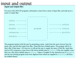
This presentation explores the complexities of Input/Output (I/O) systems within operating systems, which represent the largest and most intricate subsystems. It covers essential topics, including hardware principles, software methods for I/O activities, device driver organization, and specific types of devices, such as character and block transfer devices. The presentation delves into Direct Memory Access (DMA) operations, programmed DMA, and the foundational principles of I/O software, emphasizing efficiency, device independence, error handling, and structured device access.

E N D
Input and Output CS502 Operating SystemsFall 2006 (Slides include materials from Operating System Concepts, 7th ed., by Silbershatz, Galvin, & Gagne and from Modern Operating Systems, 2nd ed., by Tanenbaum) Input & Output
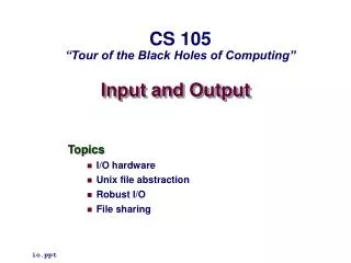
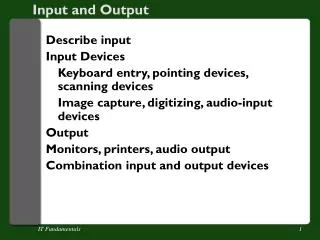
Overview • What is I/O? • Principles of I/O hardware • Principles of I/O software • Methods of implementing input-output activities • Organization of device drivers • Specific kinds of devices (Silbershatz, Chapter 13) Input & Output
I/O • The largest, most complex subsystem in OS • Most lines of code • Highest rate of code changes • Where OS engineers most likely to work • Difficult to test thoroughly • Make-or-break issue for any system • Big impact on performance and perception • Bigger impact on acceptability in market Input & Output
Memory Device Device Hardware Organization (simple) memory bus CPU Input & Output
Ether-net SCSI USB Modem Soundcard Printer Mouse Key-board Hardware Organization (typical Pentium) Main Memory AGP Port Level 2 cache CPU Bridge Graphics card Moni-tor ISA bridge PCI bus IDE disk ISA bus Input & Output
Kinds of I/O Devices • Character (and sub-character) devices • Mouse, character terminal, joy stick, some keyboards • Block transfer • Disk, tape, CD, DVD • Network • Clocks • Internal, external • Graphics • GUI, games • Multimedia • Audio, video • Other • Sensors, controllers Input & Output
Controlling an I/O Device • A function of host CPU architecture • Special I/O instructions • Opcode to stop, start, query, etc. • Separate I/O address space • Kernel mode only • Memory-mapped I/O control registers • Each register has a physical memory address • Writing to data register is output • Reading from data register is input • Writing to control register causes action • Can be mapped to user-level virtual memory Input & Output
Character Device (example) • Data register: • Register or address where data is read from or written to • Very limited capacity (at most a few bytes) • Action register: • When writing to register, causes a physical action • Reading from register yields zero • Status register: • Reading from register provides information • Writing to register is no-op Input & Output
Block Transfer Device (example) • Buffer address register: • Points to area in physical memory to read or write data or • Addressable buffer for data • E.g., network cards • Action register: • When writing to register, initiates a physical action or data transfer • Reading from register yields zero • Status register: • Reading from register provides information • Writing to register is no-op Input & Output
DMA(Direct Memory Access) • Ability to control block devices to autonomously read from and/or write to main memory • (Usually) physical addresses • (Sometimes) performance degradation of CPU • Transfer address • Points to location in physical memory • Action register: • Initiates a reading of control block chain to start actions • Status register: • Reading from register provides information Input & Output
Direct Memory Access (DMA) Operation of a DMA transfer Input & Output
Programmed DMA physicalmemory DMA controllerFirst control block disk controls … operationaddress Count control infonext operationaddress Count control infonext operationaddress Count control infonext Input & Output
Programmed DMA (continued) • DMA control register points to first control block in chain • Each DMA control block has • Action & control info for a single transfer of one or more blocks • Data addresses in physical memory • (optional) link to next block in chain • (optional) interrupt upon completion • Each control block removed from chain upon completion • I/O subsystem may add control blocks to chain while transfers are in progress • Result:– uninterrupted sequence of transfers with no CPU intervention Input & Output
Principles of I/O Software • Efficiency – Do not allow I/O operations to become system bottleneck • Especially slow devices • Device independence – isolate OS and application programs from device specific details and peculiarities • Uniform naming – support a way of naming devices that is scalable and consistent • Error handling – isolate the impact of device errors, retry where possible, provide uniform error codes • Errors are abundant in I/O • Buffering – provide uniform methods for storing and copying data between physical memory and the devices • Uniform data transfer modes – synchronous and asynchronous, read, write, .. • Controlled device access – sharing and transfer modes • Uniform driver support – specify interfaces and protocols that drivers must adhere to Input & Output
User Level Software Device Independent Software Device Drivers Interrupt Handlers Hardware I/O Software “Stack” I/O API & libraries (Rest of the OS) Device Dependent Device Dependent – as short as possible Input & Output
Three common ways I/O can be performed • Programmed I/O • Interrupt-Driven I/O • I/O using DMA Input & Output
Programmed I/O (Polling) • Used when device and controller are relatively quick to process an I/O operation • Device driver • Gains access to device • Initiates I/O operation • Loops testing for completion of I/O operation • If there are more I/O operations, repeat • Used in following kinds of cases • Service interrupt time > Device response time • Device has no interrupt capability • Embedded systems where CPU has nothing else to do Input & Output
Programmed I/O Example — Bitmapped Keyboard & Mouse • Keyboard & mouse buttons implemented as 128-bit read-only register • One bit for each key and mouse button • 0 = “up”; 1 = “down” • Mouse “wheels” implemented as pair of counters • One click per unit of motion in each of x and y directions • Clock interrupt every 10 msec • Reads keyboard register, compares to previous copy • Determines key & button transitions up or down • Decodes transition stream to form character and button sequence • Reads and compares mouse counters to form motion sequence Input & Output
Other Programmed I/O examples • Check status of device • Read from disk or boot device at boot time • No OS present, hence no interrupt handlers • Needed for bootstrap loading of the inner portions of kernel • External sensors or controllers • Real-time control systems Input & Output
Interrupt Handling • Interrupts occur on I/O events • operation completion • Error or change of status • Programmed in DMA command chain • Interrupt • stops CPU from continuing with current work • Saves some context • restarts CPU with new address & stack • Set up by the interrupt vector • Target is the interrupt handler Input & Output
Interrupts Input & Output
Interrupt Request Lines (IRQs) • Every device is assigned an IRQ • Used when raising an interrupt • Interrupt handler can identify the interrupting device • Assigning IRQs • In older and simpler hardware, physically by wires and contacts on device or bus • In most modern PCs, etc., assigned dynamically at boot time Input & Output
Handling Interrupts (Linux Style) • Terminology • Interrupt context – kernel operating not on behalf of any process • Process context – kernel operating on behalf of a particular process • User context – process executing in user virtual memory • Interrupt Service Routine (ISR), also called Interrupt Handler • The function that is invoked when an interrupt is raised • Identified by IRQ • Operates on Interrupt stack (as of Linux kernel 2.6) • One interrupt stack per processor; approx 4-8 kbytes • Top half – does minimal, time-critical work necessary • Acknowledge interrupt, reset device, copy buffer or registers, etc. • Interrupts (usually) disabled on current processor • Bottom half – the part of the ISR that can be deferred to more convenient time • Completes I/O processing; does most of the work • Interrupts enabled (usually) • Communicates with processes • Possibly in a kernel thread (or even a user thread!) Input & Output
Interrupt-Driven I/O ExampleSoftware Time-of-Day Clock • Interrupt occurs at fixed intervals • 50 or 60 Hz • Service routine (top half):– • Adds one tick to clock counter • Service routine (bottom half):– • Checks list of soft timers • Simulates interrupts (or posts to semaphores or signals monitors) of any expired timers Input & Output
Other Interrupt-Driven I/O examples • Very “slow” character-at-a-time terminals • Mechanical printers (15 characters/second) • Some keyboards (one character/keystroke) • Command-line completion in many Unix systems • Game consoles • Serial modems • Many I/O devices in “old” computers • Paper tape, punched cards, etc. • Common theme • CPU participates in transfer of every byte or word! Input & Output
DMA Input & Output
DMA Interrupt Handler • Service Routine – top half (interrupts disabled) • Does as little work as possible and returns • (Mostly) notices completion of one transfer, starts another • (Occasionally) checks for status • Setup for more processing in upper half • Service Routine – bottom half (interrupts enabled) • Compiles control blocks from I/O requests • Manages & pins buffers, translates to physical addresses • Posts completion of transfers to requesting applications • Unpin and/or release buffers • Possibly in a kernel thread Input & Output
DMA exampleStreaming tape • Requirement • Move data to/from tape device fast enough to avoid stopping tape motion • Producer-consumer model between application and bottom-half service routine • Multiple actions queued up before previous action is completed • Notifies application of completed actions • Top half service routine • Records completion of each action • Starts next action before tape moves too far • Result:– • Ability to read or write many 100’s of megabytes without stopping tape motion Input & Output
Other DMA examples • Disks, CD-ROM readers, DVD readers • Ethernet & wireless “modems” • Tape and bulk storage devices • Common themes:– • Device controller has space to buffer a (big) block of data • Controller has intelligence to update physical addresses and transfer data • Controller (often) has intelligence to interpret a sequence of control blocks without CPU help • CPU does not touch data during transfer! Input & Output
Digression:Error Detection and Correction • Most data storage and network devices have hardware error detection and correction • Redundancy code added during writing • Parity: detects 1-bit errors, not 2-bit errors • Hamming codes • Corrects 1-bit errors, detects 2-bit errors • Cyclic redundancy check (CRC) • Detects errors in string of 16- or 32-bits • Reduces probability of undetected errors to very, very low • Check during reading • Report error to device driver • Error recovery: one of principal responsibilities of a device driver! Input & Output
Device Drivers • Organization • Static or dynamic • Uniform interfaces to OS • Uniform buffering strategies • Hide device idiosyncrasies Input & Output
Device Drivers • Device Drivers are dependent on both the OS & device • OS dependence • Meet the interface specs of the device independent layer • Utilize the facilities supplied by the OS – buffers, error codes, etc. • Accept and execute OS commands – e.g. read, open, etc. • Device Dependent • Actions during Interrupt Service routine • Translate OS commands into device operations • E.g read block n becomes a series of setting and clearing and interpreting device registers or interfaces • Note that some device drivers have layers • Strategy or policy part to optimize arm movement or do retries; plus a mechanism part the executes the operations Input & Output
OS Responsibility to Device Driver • Uniform API • Open, Close, Read, Write, Seek functions • ioctl function as escape mechanism • Buffering • Kernel functions for allocating, freeing, mapping, pinning buffers • Uniform naming • /dev/(type)(unit) • type defines driver; unit says which device • Other • Assign interrupt level (IRQ) • Protection (accessibility by application, user-space routines) • Error reporting mechanism Input & Output
Uniform API and Buffering ExampleMemory-mapped Keyboard • /dev/kb • Device interrupt routine detects key transitions • Driver converts sequence of transitions into characters in user’s written language • Characters placed sequentially in buffer • Accessible by read() • Application calls getchar() or get() • Library routines implemented with read() • Provides uniform input stream semantics Input & Output
Buffering • DMA devices need memory to read from, write to • Must be contiguous pages • (Usually) physical addresses • Double buffering • One being filled (or emptied) by device • Other being emptied (or filled) by application • Special case of producer-consumer with n = 2 Input & Output
Installing Device Drivers • Classic Unix • Create and compile driver to .o file • Edit and re-compile device table to add new device • Re-link with .o files for OS kernel new boot file • Classic Macintosh • Submit to Apple for verification, approval, and inclusion • MS-DOS and Windows • Dynamic driver loading and installation • Special driver-level debuggers available; open device environment • Certification program for trademarking • Linux • Dynamic driver loading and installation • Open device environment Input & Output
Dynamic Device Configuration • At boot time:– • Probe hardware for inventory of devices & addresses • Map devices to drivers (using table previously created) • Load necessary drivers into kernel space, register in interrupt vector (.sys files in Windows) • Run time:– • Detect interrupt from newly added device • Search for driver, or ask user; add to table • Load into kernel space, register in interrupt vector Input & Output
Probing for devices • (Most) bridge and bus standards include registration protocol • [vendor, device ID] • OS (recursively) tests every addressable connection • If device is present, it responds with own ID • Performed both at • Boot time: to associate drivers with addresses • Installation time: to build up association table Input & Output
Alternative: Self-registration • In systems where every module or class initializes itself • At start-up time, each driver module is invoked • Checks for presence if device • If present, registers with OS its • Name • Interrupt handler • Shutdown action • Hibernate action • Sleep action • … Input & Output
Allocating and Releasing Devices • Some devices can only be used by one application at a time • CD-ROM recorders • GUI interface • Allocated at Open() time • Freed at Close() time Input & Output
User Space I/O Software(Daemons and Spoolers) • Device registers mapped into daemon VM • Controlled directly by daemon • Top-half service routine • Handles interrupts • Signals via semaphores or monitors • Bottom-half service routine • The daemon itself! • Waits for signals or monitors • Manages device and requests from outside kernel Input & Output
User Space I/O examplePrint Spooler • /dev/lpt is a “virtual” device available to every process & user • Driver causes • “Printing” to spool file • Control info to spooler daemon • Printer selection, options, and parameters • Spooler selects one print “job” at a time • Prints from spool file to physical device • Types of printing • Simple character strings separated by \n characters • Stream of PCL or inkjet commands • Postscript file • … Input & Output
Character Terminal • Really two devices • Keyboard input • Character display output • /dev/tty (Unix) or COM (Windows) • The classic input-output terminal • RS-232 standard • Modes • raw • cooked (aka canonical) – with backspace correction, tab expansion, etc. • Printed output vs. CRT display Input & Output
A special kind of DeviceThe Graphical User Interface • aka, the bitmapped display • In IBM language:– “all points addressable” • 300K pixels to 2M pixels • Each pixel may be separated written • Collectively, they create • Windows • Graphics • Images • Videos • Games Input & Output
GUI Device — early days • Bitmap in main memory • All output via library routines to bitmap • Entirely (or mostly) in user space • Controller, an automaton to do:– • D-A conversion (digital to analog video) • 60+ Hz refresh rate • “clock” interrupt at top of each frame CPU Main Memory Video Bitmap Digital toAnalog Input & Output
GUI Device — Displaying Text • Font: an array of bitmaps, one per character • Designed to be pleasing to eye • bitblt: (Bit-oriented Block Transfer) • An operation to copy a rectangular array of pixels from one bitmap to another … Bitmap A B C D E F Dog bitblt Input & Output
GUI Device – Color • Monochrome: one bit per pixel • foreground vs. background • Color: 2-32 bits per pixel • Direct vs. Color palette • Direct: (usually) 8 bits each per Red, Green, Blue • Palette: a table of length 2p, for p-bit pixels Each entry (usually) 8 bits each for RGB Input & Output
GUI Device – Cursor • A small bitmap to overlay main bitmap • Hardware support • Substitute cursor bits during each frame • Software implementation • Bitblt area under cursor to temporary bitmap • Bitblt cursor bitmap to main bitmap • Restore area under cursor from temporary bitmap • Very, very tricky! • Timing is critical for smooth appearance • Best with double-buffered main bitmap Input & Output
GUI Device – Window • A virtual bitmap • size, position, clipping boundaries • font, foreground and background colors • A list of operations needed to redraw contents • Operations to window itself:– • write(), refresh() Called by application to add/change information Called by window manager to redraw current contents Input & Output
GUI Device — Text Window • Character terminal emulated in a window • RS-232 character set and controls • /dev/tty • Operates like a character terminal with visible, partially obscured, or completely covered Input & Output