Download

1 / 41
440 likes | 676 Vues
Design A Wheeled Soccer Robot. Advisor: Dr. Abbas Fardoun Co-advisor: Dr. Khalifa Harib. Team Members ID Hamood Naji Albahal 200440205 Ahmed Mohammed Algabri 200440206 Surour Mohamed Alaraifi 200411538 Naji suliman AlSayeri 200632785 Second Semester 2008/2009. Outline.

E N D
Design A Wheeled Soccer Robot Advisor: Dr. Abbas Fardoun Co-advisor: Dr. Khalifa Harib Team MembersID Hamood Naji Albahal 200440205 Ahmed Mohammed Algabri 200440206 Surour Mohamed Alaraifi 200411538 Naji suliman AlSayeri 200632785 Second Semester 2008/2009
Outline • Project Overview • Robot Design Phases • Mechanical Design • BLDC Motor Drive Circuitry • Master-Slave Microcontrollers Communication • BLDC Motor Control • Final Design • Future Activities • Robot Testing
Project Overview • RoboCup is a worldwide competition designed to advance robotics and Artificial Intelligence. • This graduation project is about building a small size robot to join the Small Size RoboCup Championship in the next few years. • Project Objective: • Design a robot capable of movement in any direction and around itself at specific speed.
Project Overview • RoboCup Competition Rules: • The robot shall fit inside an 18 cm diameter cylinder and has a height of 15 cm. • Robots must run for two periods, each of 10 minutes with 5 minutes break. • The battery can be replaced during the break.
Mechanical Design • There are three main parts:- • Motor holder. • Wheel holder. • Chassis.
Motor Holder • First Design:- • Two pieces. • Cylinder. • Plate. • Second Design:- • One piece. • Problem: It weights more.
Motor Holder • Third Design:-
Wheel Holder • First Design:- • Long. • From outside.
Wheel Holder • Second Design:- • Short. • From inside.
Chassis • First Design:- • Circular. • Plate is from plastic. • Problem: edge breaking.
Chassis • Second Design:- • Square. • Plate is from aluminum.
Motor Connections • Maxon motors arrived with motor connection near to the motor shaft. • This design forces the motor connection to be under the chassis. • This problem was solved by opening the gear box and connecting it from the other side.
Motor Connections After Modification Before Modification(From Company)
Motor Connections Gear Box Motor
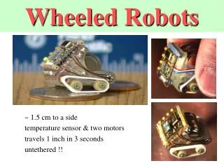
Movement of BLDC Motor • Energizing one coil • Current creates magnetic field • Field aligns along coil axis
Movement of BLDC Motor • To keep the motor rotating: • Connect other phases
Hall sensors • Most BLDC motors have three Hall sensors embedded into the stator for rotor position feedback. • 120 electrical degrees displacement from each other causes.
BLDC Circuit Description • The main purpose the circuit is to drive the BLDC motor. • BLDC motors are AC motors, but the main power supply in the project is 12V DC battery. • Circuit must be built to feed the BLDC motor by inverting the DC current coming from the battery to AC current that is supplied to the BLDC motor.
BLDC Circuit Description • The circuit consists mainly of three stages; • The first stage consists of the microcontroller which gives the 6 PWM that is needed to drive the motor. • The second stage consists of the drivers which are used as an interface between the microcontroller and the power MOSFETs. • The third stage is the three phase inverter which consists of six power MOSFETs.
BLDC Circuit Description • Two methods to build the three phase circuit: • The first method was by having all the drivers in one place and all power MOSFETs next to them. This method has some disadvantages: • Grounding problem • Wiring problem
BLDC Circuit Description • The second method: by building each driver with its two power MOSFETs separately. • Grounding problem was solved because the low side MOSFET was connected directly to the COM pin of the driver. • The layout of the circuit helped to reduce the stray inductance (reducing wiring).
ωc Vc V4 V1 Slave 4 MCU Slave 1 MCU Master MCU Slave3 MCU Slave 2 MCU V3 V2 Need of Communication • Using a standard communication protocol gives: • Reliability • Synchronization • When to transmit (write) • When to receive (read) • Wider range of data • Serial Communication
Shift Register Shift Register Buffer Register Buffer Register SPI MSB LSB MSB LSB 0 0 1 1 1 1 0 0 0 1 0 1 0 0 1 0
SDO SDI SPI Master SPI Slave1 SDI SDO ωc Vc SCK SCK SS1 SS1 SS2 SS3 V4 V1 Slave 4 MCU Slave 1 MCU SS4 Master MCU SDI SPI Slave2 SDO SCK SS2 Slave3 MCU Slave 2 MCU V3 V2 SDI SPI Slave3 SDO SCK SS3 SDI SPI Slave4 SDO SCK SS4 SPI for Robot
Stage 1 • Transfer data between one master and one slave. • The slave was without slave select. • The code counts from 1 to 7. • Problems faced:- • First information didn’t receive from master. • There is interrupt in master and slave. • The maximum data transferred are five. • Solution: • Delay after master initialization.
Stage 2 • Transfer data between one master and one slave. • The built in slave select is used. • The code counts from 1 to 7. • Problems faced:- • All data was received from master to slave (no selection). • There is interrupt in master and slave. • The maximum data transferred are five.
Stage 3 • Transfer data between one master and one slave. • Defined slave select is used. • The code counts from 1 to 7. • Problems faced:- • There is interrupt in master and slave. • The maximum data transferred are five.
Stage 4 • Transfer data between one master and two slave. • Defined slave select is used. • The code counts from 1 to 7. • Problems faced:- • There is interrupt in master and slave. • The maximum data transferred are five. • Sometimes data is interchange between two slaves.
Stage 5 • Transfer speed data between one master and one slave. • Defined slave select is used. • The speed is positive or negative • Problems faced:- • There is interrupt in master and slave. • The maximum data transferred are five. • Sometimes data is interchange between two slaves. • In this stage, we can’t integrate the slave code with BLDC motor control code.
Stage 6 • Transfer speed data between one master and one slave. • SPI interrupt is used in the slave to receive the data. • Defined slave select is used. • Problems faced:- • There is interrupt in master and slave. • The maximum data transferred are five. • Solutions: • Turn off watch dog timer. • Disadvantages: • Data is receive four times the required.
Stage 7 • Transfer speed data between one master and one slave. • External interrupt is used in the slave to receive the data. • Defined slave select is used. • Problems faced:- • The code can’t work. .
Stage 8 • Transfer speed data between one master and one slave. • SPI interrupt is used in the slave to receive the data. • Defined slave select is used. • Apply robot kinematics to master and transfer the resultant speed to slave.
Stage 9 • Using knobs(potentiometers) for master inputs and transfer data to slave. • SPI interrupt is used in the slave to receive the data. • Disadvantage: • The first speed data has some error(Accepted).
Activities • Lunching UAEU Robosoccer websites: • Official website • Facebook page • Advertising the project
Activities • Innovations’09 – AL-Ain (Dec 15th-17th) • GCC 7th cultural and science week – Jeddah (March 6th-10th) • ISMA’10 – Sharjah (April 20th-22nd)
THANK YOU FOR LISTENING ANY QUESTIONS??