Download

1 / 55
580 likes | 991 Vues
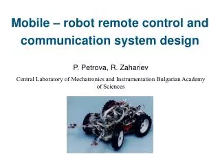
Design of Soccer-robot Wireless Communication System Graduation Project (II). Advisor: Dr. Mohammed Abdel-Hafez Done by: Ahmed Salem Al- Kaabi 200504358 Ghanem Salem Al- Shebli 200503598 Saeed Salem Al- Kaabi 200504351 Saad Abdullah Al- Ameri 200504331. Presentation Contents.

E N D
Design of Soccer-robot Wireless Communication SystemGraduation Project (II) Advisor: Dr. Mohammed Abdel-Hafez Done by: Ahmed Salem Al-Kaabi200504358 Ghanem Salem Al-Shebli 200503598 SaeedSalem Al-Kaabi 200504351 SaadAbdullah Al-Ameri200504331
Presentation Contents • Introduction • Problem Statement • Objectives • Outcomes and Deliverables • Design Wireless Communication System • Communication Protocol • Host Computer Software • Microcontroller Programming • Station Design • Final Design • System Demonstration
Problem Statement • UAEU intends to construct a robots team to participate on RoboCup competition • Fully autonomous soccer-robot team: • Computer vision • Machine learning • Communication systems • Team strategies
Objective • Design a reliable and efficient wireless communication system. • protocol of communication systems will be designed.
Outcomes and Deliverables • Design • A wireless communication system • Communication protocol • Software programs • Stations
Full explanation of the design process • Specification • Schematics of different parts of the design
Communication Protocol Design • A communication protocol is a set of rules that govern how two or more communicating parties are interacting. • Defining types of messages • Defining the action that should be taken when a message is received.
Header Destination Source Frame Type Trailer Header Destination Source Frame Type Data Trailer Communication Protocol Design • The frames are designed to be variable frames. • The header will define the beginning of the frame and the trailer will define the end. • Frame Structure:
4 0 1353253K D ? S Communication Protocol • Frame Types: • Request Frame: from the host to the stations. • Acknowledgement Frame: from the stations to the host. • Data Frame (commands): from the host to the stations. • The data will be: Distance, Speed, Angle and Kick. • Example:Distance: 13 cm. Speed: 53 cm/s. Angle: 253 Deg Kick
Host Software • The host software is a program that can send and receive frames from the stations. • The link is established by opening the serial port through the host software. • The host software was used: • To generate and sent the commands to the stations (Data frame). • To test the system • Delay test. • Protocol test.
Software Programming Design • Program planning: • Analyze • Design • Choose the interface (GUI) • Code • Test and debug • Complete the documentation
Communication settingsPort Settings With SerialPort1 .PortName = combo_port.Text .BaudRate = Val(combo_buadrate.Text) .Parity = combo_handshaking.SelectedIndex .DataBits = Val(combo_databits.Text) .StopBits = combo_stopbits.SelectedIndex .Handshake = combo_handshaking.SelectedIndex .RtsEnable = False .ReceivedBytesThreshold = 1 .NewLine = vbCr End With
Initialization process • The initialization means that the program will try to insure that the station can receive data packets. • This will be done by sending request packet for each station and wait for its acknowledgment. • The user will be able to send commands either manually or automatically after the initialization.
Automatic Control • Automatic control is a random generation for the commands that should be sent to the stations. • The program will generate the commands and it will send them to the stations.
Testing programs • Testing programs are used to test the performance of the system. • There are 2 types of tests: • Delay Test • Protocol Test
Delay Test • The goal: To measure the round trip time between the host computer and the stations. • The Idea: • To send request frame and wait to receive the acknowledgement. • How this can be done ?! Using GetTickCount function. 2 values should be taken.
Protocol Testing • In order to choose the protocol design this program was created. • Both approaches were tested.
What is a Microcontroller • A Computer-on-a-Chip • CPU (microprocessor) • Read/Write memory • Flash memory • Read Only Memory (ROM) • Analog to digital converts • Serial Communication • …
Programming Microcontroller • Microcontroller programmed to do two step: • First Step : Select number of station • Second step: Received frame • Part one: Request frame sending Acknowledgment • Part two: Data frame Display Data in LCD
Second step: part 1 Sending
Second step: part 2 LCD Display Data
Problem Faced in Microcontroller • Initialization LCD • Microcontroller does not work with 20 MHz • Reading from three switches
Design Specifications • Represents the commands received • Display the station number • Simple Design
The Proposed Design • Station Design consists of: • RF Module Board. • MCU Prototype Board • Seven-Segment • LCD Screen • Power Unit
Steps of Design • The station was divided in to units • Each unit was studied and tested • Implement the design on the breadboard.
Steps of Design • Do the PCB design for the 7-segment circuit • Arrange the units to be as one station. • Repeat the procedure for the other stations