Download
1 / 23
230 likes | 335 Vues
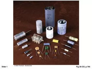
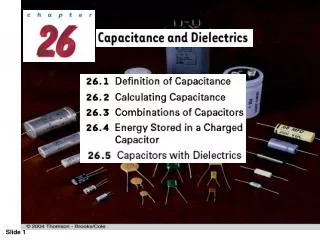
Learn about capacitance in electrical circuits, calculating capacitance, different types of capacitors, capacitor combinations, energy stored in capacitors, and the impact of dielectrics. Explore formulas and examples to deepen your understanding.

E N D
Consider two conductors carrying charges of equal magnitude but of opposite sign, Such a combination of two conductors is called a capacitor. The capacitance C of a capacitor is the ratio of the magnitude of the charge on either conductor to the magnitude of the potential difference between them: The SI unit of capacitance is the farad (F) = coulombs per volt, Fig 26-CO, p.795
26.2 CALCULATING CAPACITANCE • Parallel-Plate Capacitors A parallel-plate capacitor consists of two parallel conducting plates, each of area A, separated by a distance d. When the capacitor is charged by connecting the plates to the terminals of a battery, the plates carry equal amounts of charge. One plate carries positive charge +Q, and the other carries negative charge -Q. The value of the electric field between the plates is
The capacitance of a parallel-plate capacitor is proportional to the area of its plates and inversely proportional to the plate separation Fig 26-3a, p.799
Example A parallel-plate capacitor has an area A = 2.00 x 10⁴ m2 and a plate separation d = 1.00 mm. Find its capacitance. C = 8.85 x 10⁻¹² (C2/N.m2) . 2x 10⁻⁴(m2)/ 1x 10⁻³ (m) 1.77 x 10⁻¹² F = 1.77 pF Fig 26-3b, p.799
2. The Cylindrical Capacitor A cylindrical capacitor consists of a solid cylindrical conductor of radius a and length surrounded by a coaxial cylindrical shell of radius b. Fig 26-6, p.801
3.The Spherical Capacitor A spherical capacitor consists of an inner sphere of radius a surrounded by a concentric spherical shell of radius b.
26.3 COMBINATIONS OF CAPACITORS Parallel Combination Let us call the maximum charges on the two capacitors Q 1 and Q 2 . The total charge Q stored by the two capacitors is Q= Q1+Q2 Q2= C2 V Q1= C1 V The equivalent capacitor Q= Ceq V Ceq V= C1 V+ C2 V Ceq= C1 + C2
Series Combination Fig 26-10, p.804
Example : Find the equivalent capacitance between a and b for the combination of capacitors shown in Figure Fig 26-11, p.806
26.4 Energy stored in a charged capacitor Suppose that q is the charge on the capacitor at some instant during the charging process. At the same instant, the potential difference across the capacitor is V = q/C. We know that the work necessary to transfer an increment of charge dq from the plate carrying charge -q to the plate carrying charge +q (which is at the higher electric potential) is
This result applies to any capacitor, regardless of its geometry. We see that for a given capacitance, the stored energy increases as the charge increases and as the potential difference increases
Energy stored in a parallel-plate capacitor For a parallel-plate capacitor, the potential difference is related to the electric field through the relationship V = Ed.. The capacitance is given by By substituting The energy per unit volume known as the energy density, is The energy density in any electric field is proportional to the square of the magnitude of the electric field at a given point
26.5. Capacitors with Dielectrics Dielectric is a non-conducting material, such as rubber, glass, or waxed paper. When a dielectric is inserted between the plates of a capacitor, the capacitance increases. If the dielectric completely fills the space between the plates, the capacitance increases by a dimensionless factor k , which is called the dielectric constant.
For a parallel-plate capacitor, we can express the capacitance when the capacitor is filled with a dielectric as We see that a dielectric provides the following advantages: • Increase in capacitance • Increase in maximum operating voltage • Possible mechanical support between the plates, which allows the plates to be close together without touching, thereby decreasing d and increasing C