Download
1 / 26
280 likes | 315 Vues
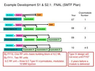
Structural and thermal analysis of a cryomodule, including stress on components under varying loads, temperature differentials, and cool-down rates. Material properties and thermal shield analysis are discussed.

E N D
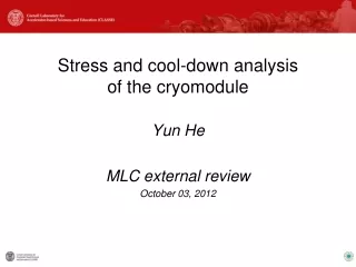
Stress and cool-down analysisof the cryomodule Yun He MLC external review October 03, 2012
Outline • Structural analysis • Weight of module and its sub-assemblies • Deformation/stress/frequency of HGRP under beamline weight • Deformation/stress/buckling of vacuum vessel under coldmass weight & vacuum • Stress on cavity flexible support due to differential thermal contractions • Cool-down thermal analysis • Asymmetric cooling on 40K shield • Material properties as a function of temperatures • 40K thermal shield temperature/stress during cool-down • Heat loads from conduction and radiation • Heat loads from conduction and radiation on posts and shield • Heatinleakfrom conduction through warm-cold transition beampipes Yun HE, MLC External Review
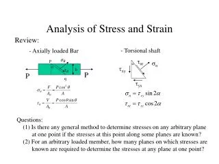
Structural analysis • Weight of module and its sub-assemblies • Deformation/stress/frequency of HGRP under beamline weight • Deformation/stress/buckling of vacuum vessel under coldmass weight & vacuum • Stress on cavity flexible support due to differential thermal contractions Yun HE, MLC External Review
Weight of module and its sub-assemblies Cold mass 3 Ton Cryomodule 7 Ton
Outline of structural analysis • Deformation/stress of HGRP under 1 ton beamline weight • Material: Ti grade 2, Ф 0.28 m ID x 9.5 mm wall x 9.65 m L • Deformation/stress of vacuum vessel under 3 ton cold mass weight & vacuum • Material: Carbon steel, Ф 0.96 m ID x 9.5 mm wall x 9.15 m L • LHe vessel cooled faster than HGRP, causing differential thermal contraction • Material: Ti grade 2 Yun HE, MLC External Review
Structural analysis of HGRP Deformation and natural frequency Max. 0.1 mm displacement Natural frequency ~ 89.1 Hz > 60 Hz • Conclusion: • Acceptable vertical displacement • May use shims to compensate the different vertical displacement at various locations • Vibration safe; may add stiffening rings if needed Yun HE, MLC External Review
Structural analysis of HGRP Stresses • Material yield strength: • 276 MPa @room temperature • 834 MPa @cryo temperature • Conclusion: • Plenty safety margin Max. stress: 26 MPa Yun HE, MLC External Review
Structural analysis of vacuum vessel Deformation Cross-section of top ports Right port Middle port Left port • Max vertical displacement : 0.38 mm • Adjustment on suspension brackets will compensate these vertical displacements Yun HE, MLC External Review
Structural analysis of vacuum vessel Deformation before/after pump-down Before pump-down After pump-down (1 atm external pressure applied) • Change in vertical position after pump-down would cause cavity to shift horizontally by 0.3 mm Yun HE, MLC External Review
Structural analysis of vacuum vessel Buckling analysis Pre-stress from structural analysis (3 ton load + 1 atm external pressure) 1st mode deformation Critical load for the onset of buckling: 6.2 X applied loads So, buckling unlikely - safe Yun HE, MLC External Review
Cavity flexible support model, boundary conditions Weightforce of 20 kg cavity shared by 2 supports A: FZ=100 N B: ΔZ=0 C: ΔY=1 mm Fixed top surface on HGRP Displacement caused by 300K to 2K temperature differential between cavity and HGRP, though it is an unlikely case In reality, cool-down is well controlled to maintain temperature differential less than 20 K, see Eric’s talk Displacement under different temperature differentials/ranges between cavity and HGRP Thermal expansion rate of Ti Yun HE, MLC External Review
Cavity flexible support sensitivity check of stress vs. cool-down rate Max stress 460 MPa, caused by 1 mm displacement • In reality, the temperature differentials are controlled within 20K, hence the stress would be much lower • At low temperature • Differential displacement small • Yield strength high Case studies of stresses under different temperature differentials/ranges between cavity and HGRP Yun HE, MLC External Review
Cavity flexible support stress @ normal operations Vertical displacement caused by weight of cavity <0.001 mm Max stress caused by weight of cavity Yun HE, MLC External Review
Cool-down thermal analysis • Asymmetric cooling on 40K shield • Material properties as a function of temperatures • 40K thermal shield temperature/stress during cool-down Yun HE, MLC External Review
Cool-down analysis of 40K shield Model & thermal interfaces • He gas cooling being on one side causes thermal gradient and shield distortion • He gas cooling rate 4 K/hr for normal cool-down procedure • Simulate: • With a cooling rate of 4K/hr • Temperature profile • Thermo-mechanical stresses and distortion • Scenario w/ faster cool-down rate @20K/hr Conduction 300K He gas Radiation from 300K He gas Yun HE, MLC External Review
Material properties as a function of temperature Used material data from NIST for calculations Yun HE, MLC External Review
Cool-down analysis of thermal shield Boundary conditions @ steady state 1.25 W/m2radiation flux rate from room temperature @ steady state Experimental data from CERN Heat transfer coefficient 1100 W/m2-K of He gas in extruded pipe @ steady state 1 W/panel (over-estimated) heat load from semi-rigid cables SS 304L G10 Al 6061 T6 Cu OFHC Al 1100-H14 5K Ti grade 2 Yun HE, MLC External Review
Cool-down analysis of 40K shield Boundary conditions for transient analysis Radiation heat flux rate set differently in 3 zones depends on their temperatures with a lapse of time delay - colder, top/bottom, far end He gas heat transfer coefficient is a function of temperature, hence a function of time Yun HE, MLC External Review
Cool-down analysis of 40K shield Temperature distributions and trends Temperature @15hr, when temperature gradient reaches max. ∆T=13oC, for a duration of ~30 hrs Temperature @75hr, when temperature reaches equilibrium, ∆T=3oC Max. ∆T=55 oC @7 hr Yun HE, MLC External Review
Cool-down analysis of 40K shield Deformation @15hr Temperature profile @15hr was loaded Y axis X axis Z axis Yun HE, MLC External Review
Cool-down analysis of 40K shield Stress @15hr Max. von-Mises stress 45 MPa @ fingers Max. shear stress 30 MPa @ fingers Conclusion: Shield safe for normal cool-down operations Material strength Yun HE, MLC External Review
Cool-down analysis of 40K shield Stress @faster cooldown rate 20K/hr • Prototype testing • Accidental faster cool-down Max. 60 MPa @ finger corners, safe Conclusion: Shield safe still safe Yun HE, MLC External Review
Heat loads from conduction and radiation • Heat loads from conduction and radiation on posts and shield • Heat inleak from conduction through warm-cold transition beampipes Yun HE, MLC External Review
Heat transfer from room temperature • Conduction via G10 tube • Radiation from 300K to 40K shield Conduction 300K Radiation G-10 tube 40K 5K 2K Yun HE, MLC External Review
Heat loads @ steady state Heat loads on middle section, 1/3 of the shield Compared with ENS’s back-of-the envelope calculation 1.569 W/cm @300K-40K 5K 6.5K Yun HE, MLC External Review
Beamline warm-cold transitions for prototype – Heat inleaks Gate valves will be at 80 K Warm-cold transition, wall 1.65mm Will have sliding joints on beamline outside module to accommodate beamline shifts at cold 300K 300K 80K 80K Heat leak from 300K to 80K: 1.3 W Heat leak from 300K to 80K: 5 W Yun HE, MLC External Review