Download
1 / 20
200 likes | 349 Vues
MICE Magnet Cool Down and Other Issues. Michael A. Green Lawrence Berkeley Laboratory Berkeley CA 94720. Issue to be Covered in this Report. The methods for cooling down of the three types of MICE coils at RAL Cool down using a helium compressor and a liquid nitrogen heat exchanger

E N D
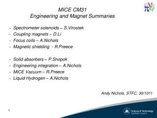
MICE Magnet Cool Downand Other Issues Michael A. Green Lawrence Berkeley Laboratory Berkeley CA 94720 CM-22 Magnet Issues, 6 June 2008
Issue to be Covered in this Report • The methods for cooling down of the three types of MICE coils at RAL • Cool down using a helium compressor and a liquid nitrogen heat exchanger • The proposed transfer line LBNL will provide to Fermilab and RAL for cooling the magnets • The position of the tracker magnet feeds and vents and the proposed transfer line • The location of the magnet power supplies and the length of the power cables CM-22 Magnet Issues, 6 June 2008
Tracker Magnet Cold Mass w/o Cover Coil M2 Coil E2 Center Coil Coil M1 Coil E1 Space for LHe The space outside of the coils is filled with 200 liters of helium. CM-22 Magnet Issues, 6 June 2008
Tracker Magnet Cold Mass with Welded Cover Magnet cooling is between the cover plate and the coils. The space inside is filled with liquid helium. The cool down gas flows in the same space. The cover plate gets colder faster than the magnet mandrel and the coils. CM-22 Magnet Issues, 6 June 2008
Tracker Magnet Simplified Heat Flow Diagram V = ~1000 L of LN2 V = ~600 L of LHe Cooling is supplied to the helium space between the cover plate and the mandrel. There is a 70 to 90 K DT restriction between the cover plate and the coil mandrel. CM-22 Magnet Issues, 6 June 2008
Coupling Magnet Cold Mass • There is no space for cooling tube on the inside RFCC magnet or at its ends. • The coupling magnet is cooled using tubes attached to the cover plate. • The magnet is cooled down using the same tubes that keep the magnet cold. • This poses problems because the cover plate is thin compared to the magnet. CM-22 Magnet Issues, 6 June 2008
Coupling Magnet Simplified Heat Flow Diagram V = ~600 L of LN2 V = ~450 L of LHe Coupling coil cool down tubes are assumed to be attached to the magnet cover plate. There is a 50 to 60 K DT restriction between the cover plate and the coil mandrel. CM-22 Magnet Issues, 6 June 2008
Focusing (AFC) Magnet Cold Mass It is proposed that the coupling magnet be cooled from the outside of the coils. The cool-down tubes could be on the mandrel. CM-22 Magnet Issues, 6 June 2008
Focusing (AFC) Magnet Simplified Heat Flow Diagram V = ~450 L of LN2 V = ~320 L of LHe The cool down tubes are assumed to be attached to the mandrel. This would make any coil cool down restrictions totally unnecessary. CM-22 Magnet Issues, 6 June 2008
Cool Down with Dewars or an LN2to Helium Heat Exchanger • Magnet weld stress is an issue when the cover plate temperature is colder than the mandrel. • When the tracker magnet is at room temperature (TM = 293 K) the DT between the cover plate and the mandrel must be <60 K. When TM is < 180 K, the DT can be >100 K. The DT between the RFCC magnet cover plate and its mandrel must also be controlled. • If the AFC magnet is cooled down with cooling tubes on the mandrel section between the coils, the DT is not a problem at all. CM-22 Magnet Issues, 6 June 2008
Simplified He Temperature Controlusing a Compressor and LN2 T = TM - 60 K TM Magnet Mass up to 1900 kg The use of a LN2 to helium gas heat exchanger is the most efficient way of controlling the cooling from 293 K to 85 K using liquid nitrogen as a coolant for the cool down. CM-22 Magnet Issues, 6 June 2008
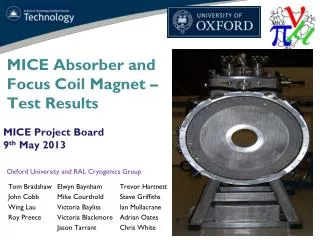
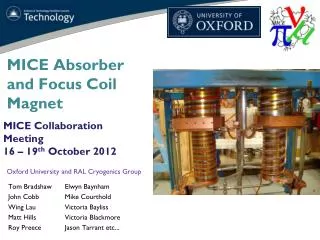
Finished Tracker Magnet on Pump PT-415 Cooler Hoses from Compressor Magnet Xmas Tree Cold Mass Support Warm Bore Magnet Stand CM-22 Magnet Issues, 6 June 2008
Tracker Magnet He Feed and Vent PT-415 Cooler PT-415 Cooler Valve Ball Valves for Cool Down Relief Valves Rupture Disc CM-22 Magnet Issues, 6 June 2008
Proposed LBNL Transfer Line • LBNL must provide a cryogenic transfer line to Fermilab so that the tracker magnet magnetic field measurements can be done there. • It is proposed that LBNL provide two cryogenic transfer lines. One is to be used at Fermilab while the other is to be used at RAL. • The dimensions of the proposed line is shown on the next page. Are these dimensions acceptable for the MICE hall at RAL? CM-22 Magnet Issues, 6 June 2008
Proposed Helium Transfer Line 2032 mm 851 mm 2438 mm The drawing dimensions are inches. CM-22 Magnet Issues, 6 June 2008
Power Supply Location and Cable Lengths • A proposed location for the two tracker magnet power supply racks at MICE has be selected. • It is believed that that the power supplies and rapid discharge diodes for all of the MICE magnets can be housed in a total of three racks. • Power for the power supplies and their controllers is needed at the rack location. City water and drain piping for the cooling of the rapid discharge diodes (only when they are on) must also be provided at the rack location. CM-22 Magnet Issues, 6 June 2008
MICE Plan View Showing Channel MICE Cooling Channel Power Supply Racks CM-22 Magnet Issues, 6 June 2008
Tracker Magnet Power Supply Racks 60 A Power Supply 300 A Power Supply controller 300 A Power Supply Rapid Discharge Diodes CM-22 Magnet Issues, 6 June 2008
Magnet Cable Numbers and Lengths • Cables made for one lab may not be transported to another lab. The lengths and Safety regulations are different for each laboratory. • For the MICE the following cable lengths apply: • The cable length given above are not exact, the trench location and size are important factors. • For both trackers, a total of fifteen 300 A cables are needed. This includes (three 1-m, three 2-m, three 6-m, and six 17-m). A total of eight 60 A cables are needed. This includes (two 2-m, two 6-m, and four 17-m). • For both coupling magnets, a total of six 300 A cables are needed. This includes (two 2-m, two 10-m, and two 13-m). • For the three focusing magnets, a total of eleven 300 A cables are needed. This includes (four 1-m, three 2-m, one 6-m, two 9-m, and one 16-m). CM-22 Magnet Issues, 6 June 2008
Concluding Comments • A method for cooling down the tracker magnets has been developed. This method can be applied to the other magnets in MICE. • A common vertical location for the magnet feeds should be developed so that one transfer line design can be used to cool down all of the MICE magnets. • The magnet power supplies and rapid discharge resistors can be located in three racks. These racks can all be in the same location. Power and non-interruptible cooling water should be available at the power supply racks. CM-22 Magnet Issues, 6 June 2008