Download
1 / 57
570 likes | 687 Vues
The latest advancements in the MICE coupling solenoid magnet project at the Harbin Institute of Technology are highlighted. Key updates include the adjustment of coil dimensions for enhanced spacing, ongoing coil winding system construction, and formalization of the collaboration agreement with LBNL. Significant engineering designs have been updated, including stress analyses and improvements to the quench protection system. 2-D and 3-D simulations regarding winding tension effects are being conducted. The project aims to optimize thermal and magnetic performances.

E N D
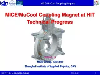
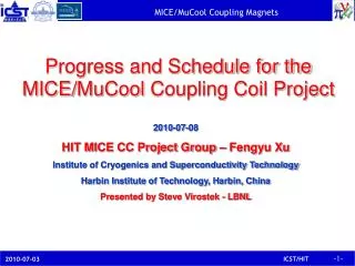
Progress on the MICE Coupling Solenoid Magnet October 8, 2007 Institute of Cryogenics and Superconductivity Technology Harbin Institute of Technology, China
Progress • The inner coil radius was changed from 744 mm to 750 mm to allow more space between the coil inner side and the inner vacuum chamber. The engineering design was updated accordingly. • The coil winding system is under construction with the funds from HIT. • The prototype coils were designed. • The formal collaboration MOU between LBNL & HIT was developed and signed by both last June. The formal Addendum to the MOU between LBNL and HIT, and the Technical Agreement for the MICE/MUCOOL coupling magnets was developed and signed in September. • The formal proposal for MICE project to the Ministry of Science and Technology of China was submitted by HIT at the end of this June with SOA and MOU from MICE collaboration and LBNL.
The engineering design on the coupling magnet has been further updated and detailed. • Stress analyses on the vacuum vessel and cold mass supports were completed. • Improvement on quench protection programming with quench back, and optimization of the quench protection circuit design are underway. • The fabrication plan (e.g. winding procedure and tooling, and assembly procedure and tooling etc.) is further detailed. • For coil assembly, study on effects of coil winding tension, banding applied to the outer surface of the coil and the possible inclusion of slip planes at the insulation interfaces to the mandrel are being carried out. 2-D simulations on effects of slip planes at the insulation interfaces to the mandrel in the coil assembly were completed. 3-D simulations on effects of coil winding tension and banding applied to the outer surface of the coil is almost done. • Test for thermal properties of AIN and contact resistance among AIN, indium film and cooler cold head by PTR-407 in ICST is under way. The test station was designed, built and under commissioning.
Updated Design • Basic design parameters for the coupling coil • Main structure design parameters • Heat loads • Magnetic fields on coupling coil • Effect of stray fields on HTS leads and cryocoolers • Magnetic forces on coupling coil • Passive Quench protection design • Winding system design and construction • Prototype coils’ design • Vacuum chamber design
Fig. Cross-section of the cold mass for a coupling coil with 750mm inner radius
The self inductance of the coil increases from 564 H to 593 H (~5%) , and the magnet stored energy increases about 4% with the coil inner radius increasing from 744 mm to 750 mm. The peak induction in the coil and the temperature margin dropped by a small amount. The space between the cold mass and the inner thermal shield increased from 9.7 mm to 15 mm, which will be helpful in reducing the heat load at 4.2K. Comparisons
FEA results on stress and deflection of the coil assembly Total deflections [m]
Shear stress in the RZ cross-section of coupling magnet (Pa)
FEA results on temperature distributions for the coil assembly ΔT between the hot spot on the 750mm IR coil inner surface (at the high field region) and the inner surface of the helium tubes is 0.082K (less than 0.1K) at state steady operation for four cooling tubes in parallel (26x2).
ΔTand AC loss with time during charging process *AC loss in banding is not included. A normal charge time is 13860 seconds (based on a charge at the full voltage delivered by the power supply) .
ΔTand AC loss with time during fast discharging process *AC loss in banding is not included. A rapid discharge has a time constant of 3600 seconds (based on a peak voltage across the coil of 33.6 V when a resistance of 0.16 ohms is put across the coil at the power supply).
The thermal stress still dominates as compared to the magnetic coil forces During cool down from 300K to 4.2K, the coil center moves inward about 2.9 mm. When powered to 210 A, the coil center moves outward about 0.9 mm Most stress in the coil is less than 40 MPa due to thermal contraction and increases when powered. The peak stress is about 94 MPa in the corners and where the peak field is located The maximum stress due to cool down in the Al coil case is at the corners (92 MPa) and increases to 142 MPa when powered, which is less than the allowable stress of 6061T6 Al at 4.2K (~161 MPa) The hot spot appears at the high field point in the coil winding for normal operation, and the ΔT of 0.082K is acceptable Due to the reduced thickness of Al banding, the ΔT between the hot spot in the coil and the cooling helium decreases (even though the AC losses increase for the larger diameter coil) Comments The stress & deflection in the coil and the AC losses changed only slightly.
Heat loads at 60K Cryomech PTR415, 55W/60K for the 1st-stage, 1.5W/4.2K, 50Hz for the 2nd- stage; with a remote valve motor, at least 10% deduction to 1.35W/4.2K.
Heat loads at 4.2K* * The heat load for the IR744 is only different from the IR750 coil in the radiation heat load.
Cryocoolers He condenser Vacuum chamber He collection box Cooling circuit Cover plate Al coil mandrel Coil Heat shields LHe distribution container Cold mass supports Al banding G-10 insulation • MICE Coupling magnet engineering design Pro/E drawing by C.S.Liu
Cryocoolers Power leads Thermal shields and intercepts Cold mass supports Vacuum vessel He condenser He cooling pipes Coil assembly Pro/E drawing by C.S.Liu
Magnetic fields on coupling coil 240MeV/c (T) 200MeV/c (T) Magnetic Field around Coupling Coil at Flip Mode
200MeV/c (T) 240MeV/c (T) Magnetic Field around Coupling Coil at Solenoid Mode
2.613T 2.176T Coupling coils Fig. 3-1-1 Magnetic field on the axis of MICE cooling channel at flip mode
2.634T 2.197T Coupling Coils Coupling Coils Fig. 3-1-2 Magnetic field on the axis of MICE cooling channel at solenoid mode
Effect of Stray Magnetic Field on HTS Leads B [T] only considering Coupling Coil B [T] in MICE channel R=1458mm, Z=-164mm, B=0.313T (0.310T)
Effect of stray magnetic field on cooler drive motor B (T) only considering coupling coil B (T) in MICE channel R=1.74m, Z=0.05m, t=±0.11m
The maximum field on the coupling coil is 7.40Tfor the 240MeV/c flip mode (7.44T for 744mm IR coil), which is on the inner surface of the coil. The influence of magnetic field on the coupling coil from other coils in the channel is not much (within 2 percent). The effects of stray magnetic fields on the HTS leads and cryocoolers are nearly unchanged for the 750 mm coil design compared with the 744 mm coil. Comments
Longitudinal magnetic forces on coupling magnet When all coils in the MICE channel operate normally (kN) When various coil circuits quench at 240MeV/c (kN)
When current leads are reversed in 240MeV/c flip mode (kN) Note: Negative force is toward the channel center, and positive force is away from the channel center. • The maximum magnetic force on the coupling coil is 416.4 kN (399.4 kN for 744mm IR coil), towards the channel center. • The design longitudinal load for the cold mass supports is assumed to be 500kN(including some contingency). • The cold mass support design is the same as that for the 744 mm coil.
Passive Quench protection system Calculation Results for Rp=5Ω Due to increased self-inductance and magnet stored energy, the maximum internal voltage during quench is higher for the new design.
spool Winding machine Automatic guider Tension feedback Dereeler (an unwinding facility) Winding system design & construction • The coil winding system design based on a wet winding process using filled epoxy is essentially complete. Safety interlocks will prevent overtensioning or breakage. A conductor guidance system has been designed.
Spider support for coil winding The winding pre-tension is set at ~100MPa.
送风口 电源 电源 线轴 电源 送风口 洁净间 气源 电源 吸尘器 拉门 换鞋柜 鞋柜 拉门 水池 更衣室 衣柜 吹淋室 配电柜 吹淋 A B Winding Hall • Winding System • Soldering tooling • Movable crone • Work bench • Window Drawing by Liu ShouYin
Conversion PLC PC VFC VFC Driver Position Sensor M ~ M ~ M ~ PG PG Tension Regulation Dereeler Main Shaft Guider Schematic of Control System
Switch between automatic and manual Switch between forward and reverse rotation Stop at anytime by one key or button All motors are of power-failure brake type The tension system can stably operate in the range of 5 to 50kg Wire length will be auto-counted The status of each component is monitored The HMI is not finished; a historical table and background database will be added Function of the Control System
Coil Parameters Design of prototype coils Coil I: small coil; Coil II: prototype coil
Small coil • It is proposed that a small superconducting coil be wound using about 5 km of tracker solenoid conductor • This coil winding would be used to test and debug the winding machine and the wire tensioning device • The small test coil will demonstrate: fabrication of coil splices during winding, the wet winding process, conductor connections for coil voltage taps and the quench protection system • The test coil will be high potted to a voltage that is higher than that required for the coupling solenoid (>5 kV) • The coil can be run in liquid helium at ICST
Main structure design parameters Basic design parameters for small coil
285 3 5 5 8 1 8 3 25.5 0.5 0.5 8 350 401
Load line for small coil The coil can be charged up to 500A using two 300A power supplies in parallel
Prototype Coil • Wind a full diameter test coil (prototype coil) with ~20 km of conductor to demonstrate the highest field and strain state of the coupling magnet in the MICE cooling channel • The purpose of the prototype coil is to test the coil under strain conditions that are greater than would be encountered in the coupling coil. Training can be done if needed. • The coil would be mounted in an ICST vacuum vessel. The magnet would be cooled using the ICST refrigerator.
Main structure design parameters Basic design parameters for Coil II
Cover Plate Banding 72 5 5 1 8 Coil 8 3 3 102 End Plate 0.5 0.5 8 G-10 Bobbin 1500 1704
Load line for prototype coil The coil can be charged up to 400A using two 300A power supplies in parallel
Coil II Due to cooling and magnet force Coil I Total deflections (m)
Z R 1500 102×72 350 25.5×285 Coil I Coil II Von Mises stress in the test coils at 210A
The magnetic induction in the center of small coil is about 2.27T. The peak magnetic induction on the small coil’s inner surface is about 2.8T The maximum stress is in the banding (75.2 MPa), which is within the strength limit of Al 6061-T6 With 2-sectioned and 0 resistor, the hot spot temperature is about 65K, and the peak internal voltage is about 135V Comments for Coil I at 210A Comments for Coil II at 210A • The magnetic induction in the center of prototype coil is about 0.65T • The peak magnetic induction in the coil’s inner surface is about 3.91T • The maximum stress is in the banding (93.9 MPa), which is within the strength limit of Al 6061-T6 • With 4-sectioned and 0 resistor, the hot spot temperature is about 65K, and the peak internal voltage is about 135V