Download
1 / 36
360 likes | 473 Vues
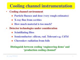
Progress on the MICE Cooling Channel Magnets. Michael A. Green Lawrence Berkeley National Laboratory 28 June 2005. 3D View of the MICE Cooling Channel. Coupling Magnet Cryostat. AFC Module. RFCC Module. Courtesy of S. Yang Oxford University.

E N D
Progress on the MICE Cooling Channel Magnets Michael A. Green Lawrence Berkeley National Laboratory 28 June 2005
3D View of the MICE Cooling Channel Coupling Magnet Cryostat AFC Module RFCC Module Courtesy of S. Yang Oxford University
Three Quarter Section View of the MICE Cooling Channel Courtesy of S. Yang Oxford University Coupling Coil Focusing Magnet Coil
Half Section View of theMICE Cooling Channel Liquid Hydrogen Absorber Focusing Magnet Coil 201 MHz RF Cavities Coupling Coil Courtesy of S. Yang Oxford University
Cooling Channel Magnet Progress • The cooling channel consists of three AFC modules and two RFCC modules. • This report will discuss the progress made since the last meeting on the focusing magnet and the coupling magnet. • Progress on the tracker magnet (detector magnet) will not be presented. This information was presented on June 27th.
The MICE AFC Module Courtesy of S. Yang Oxford University
The Center of the MICE AFC Module Gas He Pipe Coil Cover Plate S/C Coil #1 S/C Coil #2 LH2 Absorber Hydrogen Window LH2 Pipes Safety Window Magnet Mandrel Liquid Helium Feed Pipe Courtesy of S. Yang Oxford University
The Focusing Magnet Parameters These are the worst cases based on p = 240 MeV/c and b = 420 mm
Focusing Magnet Progress • Progress has been made on the focusing magnet quench protection system and in the power system for the magnets. • The quench simulations show that the focusing magnets can be passively quenched without a formal quench protection system. • The three focusing magnets can be connected in series. External diodes and resistors are used to control the voltages across the coils.
Focusing Magnet Mandrel Tafter a Quench in the Flip Mode • Max T = 51.9 K • Min T = 4.41 K • Quench Time = 4 s • Istart = 250.8 A • = ~0.80 p = 240 MeV/c b = 420 mm Courtesy of H. Witte Oxford University
Focusing Magnet Mandrel Tafter a Quench in the Non-flip Mode • Max T = 41.7 K • Min T = 4.69 K • Quench Time = 4 s • Istart = 130.3 A • = ~0.80 p = 240 MeV/c b = 420 mm Courtesy of H. Witte Oxford University
Focusing Magnet Mandrel Hot Spot Tas a Function of Time • Max T = 51.9 K • Min T = 4.41 K • Quench Time = 4 s • Istart = 250.8 A • = ~0.80 p = 240 MeV/c b = 420 mm Quench back occurs. Courtesy of H. Witte Oxford University
Cavity RF Coupler Coupling Magnet Dished Be Window RF Cavity Module Vacuum Vessel Magnet Vacuum Vessel Vacuum Pump The MICE RFCC Module Courtesy of S. Yang Oxford University
Coupling Magnet Progress • Progress has been made on the coupling magnet quench protection system and in the power system for the magnets. • The quench simulations show that the coupling magnets can be passively quenched without a formal quench protection system. • The two coupling magnets can be connected in series, but it may be better to power the two magnets separately. Cold diodes and resistors are used to control the voltages within the coils.
Coupling Magnet Mandrel Tafter a Quench in the Flip Mode • Max T = 83.9 K • Min T = 4.21 K • Quench Time = 5 s • = ~0.92 p = 240 MeV/c b = 420 mm Courtesy of H. Witte Oxford University
Coupling Magnet Mandrel Hot Spot Tas a Function of Time • Max T = 83.9 K • Min T = 4.21 K • Quench Time = 5 s • = ~0.92 p = 240 MeV/c b = 420 mm Quench back occurs. Courtesy of H. Witte Oxford University
Coupling Coefficients between Coils Magnet Circuit Self Inductance and the Mutual Inductances in the Flip Mode Magnet Circuit Self Inductance and the Mutual Inductance in the Non-flip Mode Courtesy of H. Witte Oxford University
Conclusions from the Self and MutualInductance Calculations • Every magnet circuit in MICE is coupled to every other magnet circuit in MICE. • The charging or discharging of one magnet circuit will affect every other magnet circuit, but the power supplies can handle the effect. • A quench of one magnet circuit will not drive other magnets normal by changing the currents too much. AC losses induced by a quench do not appear to be a factor, except from mandrel heating.
Coupling between Magnet Coil Circuits and other Magnet Mandrels
Currents for Various Cases and theCoupling Coefficients Coil Currents for Various Cases where p = 240 MeV/c and b = 420 mm Coil to Mandrel Coupling Coefficients for Various Cases Courtesy of H. Witte Oxford University
Heating of the Coupling Mandrelby a Focusing Quench (Flip Mode) Courtesy of H. Witte Oxford University • Max T = 4.45 K • Min T = 4.41 K • Quench Time = 4 • = ~0.0018 p = 240 MeV/c b = 420 mm A quench of the focusing magnet circuit is unlikely to quench the coupling magnet in the flip mode.
Heating of the Coupling Mandrel by a Focusing Quench (Non-flip Mode) Courtesy of H. Witte Oxford University • Max T = 4.76 K • Min T = 4.69 K • Quench Time = 4 s • = ~0.0137 p = 240 MeV/c b = 420 mm A quench of the focusing magnet circuit may quench the coupling magnet in the non-flip mode, at high momenta.
Heating of the Focusing Mandrel by a Coupling Quench (Flip Mode) Courtesy of H. Witte Oxford University • Max T = 6.30 K • Min T = 4.22 K • Quench Time = 5 s • = ~0.0813 p = 240 MeV/c b = 420 mm A quench of the coupling magnet circuit is likely to quench the focusing magnet in either mode.
Coupling Coefficients between Magnet Circuits and Various Mandrels Courtesy of H. Witte Oxford University The quench of a cooling channel magnet circuit is unlikely to cause a quench of a tracker magnet. A tracker magnet quench won’t quench the channel magnets.
Conclusions from the Magnet Coupling Calculations • A quench of a focusing magnet is unlikely to quench any other magnet except the coupling magnet at high muon momenta in the non-flip mode. • A quench of a coupling magnet is likely to quench the focusing magnet except at low muon momenta. A coupling magnet quench will not quench the tracking magnet. • A quench of the tracker magnet is unlikely to quench any of the other magnets in MICE.
Concluding Comments • Engineering progress has been made on all of the MICE magnets and their sub-systems. • Quench calculations show that the MICE focusing and coupling magnets will quench safely. It is probable that the detector magnets will also quench safely. This will be verified before the next meeting. • A coupling magnet quench will cause the focusing magnet to quench, but a quench of the other magnets is unlikely to cause a quench of other magnets in MICE.