Download
1 / 22
320 likes | 767 Vues
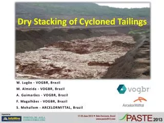
Dry Stacking of Cycloned Tailings. W. Lugão - VOGBR, Brazil M. Almeida - VOGBR, Brazil A. Guimarães - VOGBR, Brazil F. Magalhães - VOGBR, Brazil S. Mohallem - ARCELORMITTAL, Brazil. Introduction.

E N D
Dry Stacking of Cycloned Tailings W. Lugão - VOGBR, Brazil M. Almeida - VOGBR, Brazil A. Guimarães - VOGBR, Brazil F. Magalhães - VOGBR, Brazil S. Mohallem - ARCELORMITTAL, Brazil
Introduction • Tailings at ArcelorMittal Mineração’s Serra Azul Mine are currently disposed of in a tailings dam, which is at the end of its useful life. Another tailings disposal facility is required and there is no place for another conventional dam. • A drained stacking scheme was proposed, with the following advantages over conventional dams: • - It allows tailings to be stored in stacks, which poses less risk as it does not involve the storage of water; • - It will be located in an area that was occupied by a fines stockpile (sinter feed), which is why no additional land will have to be purchased; • - It allows mining operations to proceed without interruption.
IMAGE: 09-14-2007 – GOOGLE EARTH SERRA AZUL MINE TAILINGS DAM SINTER FEED
IMAGE: 07-30-2011 – GOOGLE EARTH SERRA AZUL MINE TAILINGS DAM DRY STACKING TAILINGS
DRY STACKING DRYING PONDS- OVERFLOW TAILINGS CONTAINMENT DIKE SEDIMENT Design Concept CYCLONE
WASTE PILE Design Concept A • WASTE/TAILINGS CO-DISPOSAL DRY STACKING
Internal drainage Design Concept DRAIN - SECTION JIG TAILINGS ROCK-FILL STARTER EMBANKMENT
Example: Plant level 1,030 m – tailings/waste co-disposal Design Concept A SECTION A WASTE PILE OVERFLOW / UNDERFLOW TAILINGS JIG TAILINGS UNDERFLOW TAILINGS 8m 25m 100m ROCK-FILL STARTER EMBANKMENT TAILINGS CELLS
Schematic profile (section A) Design Concept OVERFLOW/UNDERFLOW WASTE PILE UNDERFLOW DIKES JIG DIKES ROCK-FILL - STARTER EMBANKMENT
Design Concept UNDERFLOW DIKES Conception: Underflow dikes – vertical drainage!!! Conception: Overflow – drainage in top and base!!!
Pilot Tests - Cyclone UNDERFLOW TAILINGS CYCLONE
Tailings characterisation Percentfinerthan Jig Tailings Total Tailings AM01 Underflow AM02 Underflow Overflow Grainsize - millimeters
Table - Test results Table - Permeability test summary
Table 6 Parameters for materials used in stress-strain and stability analyses Table - Triaxial test results Table - Parameters for materials used in stress-strain and stability analyses
Stress-strain analysis MATERIALS FINITE ELEMENT MODEL (SIGMA) FINAL STACK CONDITION
Stability Analyses • The safety factor for the critical failure surface is 1.97 and is therefore satisfactory. Stability analysis results for waste rock/tailings co-disposal – Global – Non-Circular failure.
Operation OVERFLOW TAILINGS – DISPOSAL SEQUENCE
Situation - December 2012 DRYING PONDS ROCK-FILL - STARTER EMBANKMENT UNDERFLOW LEVEL 1000.5 m CONTAINMENT DIKE OVERFLOW LEVEL 1000 m
Final Remarks • Stability analyses have arrived at a satisfactory safety factor, assuming the long-term (drained) final stack condition; the maximum predicted subsidence in dry stacks will be acceptable even in the most critical long-term condition; • It is suggested that the cyclone system operating techniques should be reviewed, as the system is now working with overflow rates in excess of design rates. As a result, underflow requirements are being filled with jig tailings currently available at the mine for such purpose. • It is also recommended that alternative methods should be developed for carrying overflow tailings from dewatering ponds to the storage basins, including alternative deposition methods, with a view to improving the process which is currently undertaken using trucks. • An investigation campaign is programmed, composed of SPT, CPTU, Vane, permeability and laboratory tests; • ArcelorMittal will continue monitoring the performance of the system.
Thank you! • Contact: • wlugao@vogbr.com.br