Download
1 / 18
190 likes | 381 Vues
Thermal effects and their compensation in Advanced Virgo. E. Coccia 1,2 , M. Di Paolo Emilio 2 , V. Fafone 1,2 , V. Malvezzi 2 , Y. Minenkov 2 , A. Rocchi 2 , L. Sperandio 1,2 . 1 University of Tor Vergata 2 INFN Roma Tor Vergata. 46th Rencontres de Moriond 26.03.2011. Thermal effects

E N D
Thermal effects and their compensation in Advanced Virgo E. Coccia1,2, M. Di Paolo Emilio2, V. Fafone1,2, V. Malvezzi2, Y. Minenkov2, A. Rocchi2, L. Sperandio1,2. 1University of Tor Vergata 2INFN Roma Tor Vergata 46th Rencontres de Moriond26.03.2011
Thermal effects Brief introduction Compensation principle An example: Virgo+ TCS Thermal Compensation System for AdV Layout Heating pattern optimization Ring heater development Wave-front sensing Outline A. Rocchi - Rencontres de Moriond 2011- La Thuile
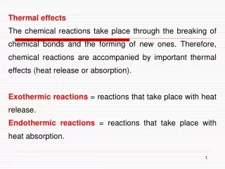
Thermal effects: introduction • High Reflectivity coating and substrate of the Test Masses absorb some (O(ppm)) power stored in the Fabry-Perot and recycling cavities. • Due to the low thermal conductivity of SiO2, a thermal gradient is established in the substrate. • Thermal lensing: • The refraction index is temperature dependent (dn/dT≠0, O(ppm/K)). • The optical path inside the substrate of the TMs is not uniform. • This is equivalent to putting a lens in the substrate of the ITMs. • Thermo-elastic deformation of the HR surface of all the TMs. 26/03/2011 A. Rocchi - Rencontres de Moriond 2011- La Thuile
[ppm] Thermal effects: consequences • Thermal lensing: wave-front distortions of the fields in the SRC and PRC cavities. • Decrease of the optical gain in the RCs; • If lensing is too strong, ITF cannot acquire the lock. • FOM: coupling losses. • Thermo-elastic deformation: changes the RoC in both ITMs and ETMs, affects the FP cavity. This effect is negligible in current detectors, but becomes relevant in advanced IFOs. • Decrease of the spot size on TMs increase of thermal noise of about 15%. 26/03/2011 A. Rocchi - Rencontres de Moriond 2011- La Thuile
Working principle of TCS Thermal lensing is only due to the temperature gradient along the radial direction. So, we can heat the peripheral of the test mass to flatten the gradient and, thus, the optical path length. 26/03/2011 A. Rocchi - Rencontres de Moriond 2011- La Thuile
Current compensation systems All use CO2 (l=10.6mm) lasers to heat the peripheral of the input test masses. CO2 Laser Gold star mask Annular heating AXICON Initial LIGO Enhanced LIGO and Virgo+ 26/03/2011 A. Rocchi - Rencontres de Moriond 2011- La Thuile
Virgo+ scheme Mirror B Mirror A Half wave plate and fixed polarizer are used for DC power control. This system does not deviate the beam impinging on the AXICON Single AXICON used to convert a Gaussian beam into an annular beam. Size of the annulus hole can be set by moving L3 To monitor the CO2 beam quality, an infrared camera has been installed on each bench. 26/03/2011 A. Rocchi - Rencontres de Moriond 2011- La Thuile
Noise from TCS • TCS can inject displacement noise into the detector. • Coupling mechanisms: • Thermo-elastic (TE) - fluctuations in locally deposited heat cause fluctuations in local thermal expansion • Thermo-refractive (TR) - fluctuations in locally deposited heat cause fluctuations in local refractive index • Flexure (F) - fluctuations in locally deposited heat cause fluctuations in global shape of optic • Radiation pressure (negligible) RIN = relative intensity noise TE TR F Present detectors already require intensity stabilization of the CO2 laser. Achievable level of intensity stabilization (10-7/√Hz) not enough to heat with CO2 directly the TM in advanced detectors (10-9/√Hz needed) compensation plates required. 26/03/2011 A. Rocchi - Rencontres de Moriond 2011- La Thuile
TCS in Advanced detectors Power absorbed by TMs is about 0.5W, wrt ~20mW in initial detectors Compensation plates shined with CO2 laser will correct thermal effects in the RCs Ring heaters will compensate HR surface deformations Green dots: heating rings Blue rectangles: CPs This set up allows to control independently the thermal lensing and the ROCs 26/03/2011 A. Rocchi - Rencontres de Moriond 2011- La Thuile
Some details HR face TM Tmap • RH at 5 cm from the anti-reflecting face of the TM to maximize the efficiency • CP diameter: 350 mm (same as TMs) • CP thickness = 35 mm • CP must be “far” from the TM. Distance fixed at 200 mm TM heated by radiation from the CP if CP-TM distance = 1 cm Symmetry axis Heat escaping from the barrel of the CP Symmetry axis 26/03/2011 A. Rocchi - Rencontres de Moriond 2011- La Thuile
CP heating pattern • The heating profile must be much more precise than in present detectors • Simple system like an axicon (Virgo-like) is not enough • Too high content of higher order modes in RF sidebands • Necessity to optimize the CP heating pattern • Linear iterative optimization process based on FEM developed, to take into account radiative coupling btw TM and CP and the presence of the RH. Uses the OPL increase as error signal. Resulting Optical Path Length Optimal heating pattern Coupling losses = superposition integral between “unperturbed” beam and single pass through thermal lensing. Residual coupling losses= 26 ppm with single axicon = 2200 ppm No TCS = 5·105 ppm 26/03/2011 A. Rocchi - Rencontres de Moriond 2011- La Thuile
Heating pattern generation: DAS Solution using known technology: modulate rings dimensions by changing distances between lenses and axicons and modulate power in each ring (Double Axicon System) • With DAS, residual coupling losses • around 102 ppm. • Residual focal length O(103 km) • -With single axicon, residual coupling • losses around 2000 ppm • Residual focal length O(102 km) 26/03/2011 A. Rocchi - Rencontres de Moriond 2011- La Thuile
Heating pattern generated by the DAS Experiment vs. simulation • The beam is split by polarization and recombined with round polarizer at 45 deg AOI. • The optical layout is very flexible! Allows to change independently the two rings: • Inner and outer diameters of each ring • Power density of each ring • Heating profile simulated with Zemax gives 200 ppm coupling losses • Experimental DAS gives 210 ppm 26/03/2011 A. Rocchi - Rencontres de Moriond 2011- La Thuile
y x z Ring heater development • Main concerns: • Stray magnetic field: AdV will use electro-magnetic actuators to control the TMs; • Vacuum compatibility. • Down-scaled prototypes with different geometries and materials realized: • Annular winding with counter-flux coils; • Toroidal winding: • Single coil; • Double coil (counter-flux). • Magnetic field measurements: • Detailed maps as a function of the position; • Frequency domain transfer function; • 3D magnetic field simulations. Annular winding Toroidal winding Measured Simulated 26/03/2011 A. Rocchi - Rencontres de Moriond 2011- La Thuile
Noise projection • Simulated a RH of 400 mm diameter and considered the magnetic field and gradient in the position of the magnets • Assumed a flat current noise of 1nA/Hz B Preliminary g = magnets symmetry m= magnetic moment m = mirror mass I = moment of inertia L = arm cavity length D = beam displacement D 26/03/2011 A. Rocchi - Rencontres de Moriond 2011- La Thuile
Materials optimization To avoid contamination from the insulation of the wire we have chosen a design with bare wire on insulated support. Under investigation: glass core aluminum core with insulating coating Aluminum samples machined and coated with: inorganic paint plasma spray with alumina diamond like coating 26/03/2011 A. Rocchi - Rencontres de Moriond 2011- La Thuile
TCS sensing scheme The full TC System to be implemented on Advanced Virgo will comprehend sensors which sample the thermal wave-front distortions within the interferometer, either from samples of the IFO beam picked off at appropriate points, or directly from the optics themselves using dedicated probe beams and servo electronics that will derive control signals from the sensors and feed them back to the heater elements. Advanced Virgo will use a Hartmann sensor developed by the University of Adelaide, that has demonstrated to have a shot-to-shot reproducibility of λ/1450 at 820 nm, which can be improved to λ/15500 with averaging (Opt. Express 15 (16), 10370-10375, 2007). Measurement taken at the Gingin HOPTF 26/03/2011 A. Rocchi - Rencontres de Moriond 2011- La Thuile
Conclusions • Thermal compensation systems proven to be efficient and reliable in initial detectors: recovered 85% of sidebands recycling gain. • In advanced detectors, thermal effects must be corrected with higher precision: • More power in the cavities; • Larger spot size on ITMs; • One more effect to take care of: TMs RoC. • Good experimental results from the DAS: • Good agreement with simulations; • Easy to assemble; • High degree of flexibility. • Ring heater design is progressing. • High sensitivity wave-front sensor identified for advanced detectors. 26/03/2011 A. Rocchi - Rencontres de Moriond 2011- La Thuile