500 MHz ELETTRA Input Power Coupler
280 likes | 482 Vues
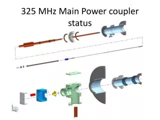
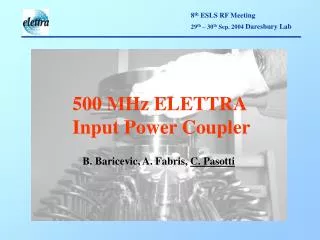
500 MHz ELETTRA Input Power Coupler. B. Baricevic, A. Fabris , C. Pasotti. IPC is a coaxial device: connected to the transition to 6 1/8” transmission line non uniform longitudinal section (from Ø 84 mm to line 6 1/8” Ø 154 mm) ceramic window for air to vacuum separation

500 MHz ELETTRA Input Power Coupler
E N D
Presentation Transcript
500 MHz ELETTRA Input Power Coupler B. Baricevic, A. Fabris, C. Pasotti
IPC is a coaxial device: • connected to the transition to 6 1/8” transmission line • non uniform longitudinal section (from Ø 84 mm to line 6 1/8” Ø 154 mm) • ceramic window for air to vacuum separation • water cooled, cooling pipes brazed in the UHV side • coupling range : 1 to 3.6
The system “IPC & connection element” had some troubles: two failures at SLS, similar events happened also at ELETTRA. The IPC has been tested at more that 200 KW of forward power. Those events happened at lower input power.
The electromagnetic parameters of the IPC coupled to the connection element (CE) to the 6 1/8” transmission line has been studied with the Ansoft HFSS v 9.1 Aims: • Try to understand the IPC + CE power limit at 500 MHz for the working condition: from the ideal coupling to the maximum mismatch. Forward power is fed in continuous wave to the IPC: power limitation comes from the maximum operating temperature the device, but mainly the insulating supports, can safely sustain • Know the EM response at signal stored into the cavity at any frequency different from the 500 MHz, that is in the HOMs frequency range: from 700 MHz up to 2.1 GHz. Other (and unwanted) signals coming from the cavity could build up a field pattern that overlaps the forward 500 MHz signal: the thermal and electric breakdown discharge threshold can be suddenly reached.
The “Elettra” cavities are not equipped with HOMs dampers. What’s happen if the beam looses some energy that resonates in the cavity? Does this signal propagate through the IPC?
The first three modes of propagation of the transmission line have been investigated TEM, TE11 and TE21. Only the TEM-like mode plays a significant role in the investigated frequency range. • Cut-Off Frequencies • 6 1/8” Port • TE11 = 876 MHz • TE21 = 1.75 GHz • TM11 = 3.49 GHz • Cavity Port • TE11 = 2 GHz
50 W, 6 1/8” coaxial port, toward the generator. Reflection coefficient ri 50 W coaxial port, outer diameter equal to the cavity equatorial port diameter. Reflection coeffcient rc
The coupling with the cavity and beam has been taken into account in the numerical result post-processing, imposing the reflection less condition for the maximum beam current ( ri=0 ). At the maximum current, the reflection coefficient rc due to the cavity and beam load is :
The total IPC power dissipation at 500 MHz, and ri=0, is distributed according to the following: • 62.4 % on the inner conductor • 24.0 % on the outer conductor • 13.6 % on the alumina ceramic window. • The copper inner and outer conductor are water-cooled. The main limiting element is the ceramic window. Taking into account the maximum alumina dissipation of 15 Watts, the IPC average power limits roughly are • 220 kW in the reflection less condition ri= 0 • 180 kW with highest reflection, no beam
The CE power dissipation at 500 MHz, and ri=0, is distributed according to the following: • 7.9 % on the inner conductor, silver plated. • 1.4 % on the outer conductor, aluminum part. • 90.7 % on the steatite support disk. • At the maximum mismatch the CE dissipation does not differ from the previous values. • The largest dissipation occurs on the insulating disk. With no external cooling, this element can tolerate 95 kW of input power. • To raise this limit the steatite disk MUST BE COOLED!
The IPC+ CE reflection coefficient exhibits two minima in the HOMs frequency range. The EM-field has a stationary behavior near to the ceramic window for the 1st minimum and near to the steatite disk for the 2nd one. At the IPC cavity port the following power causes a dissipation equivalent to that of 220 kW @ 500 MHz from the generator: 2.7 kW @ 1.5 GHz on the inner conductor (vacuum part) 9.4 kW @ 1.5 GHz on the alumina window 4.2 kW @ 1.5 GHz on the inner conductor (air part) 26.4 kW @ 2.1 GHz on the steatite disk.
For all the frequency range the maximum E-field is reached in two zones shown with red circles, in the “air part”. Pt 1 Pt 2 The connection element is very critical: it experiences the mismatching due to the IPC external conductor step!
The electric field at the HOM frequency can add to that at 500 MHz if the phases are the correct ones. The net result, in the worst scenario, is a local increase of the E-field and an increasing risk of electric breakdown. Few Watts picked up by the IPC @1.5 GHz + 110 kW @ 500 MHz= the breakdown threshold is reached in point 2!!!
There is a huge stationary phenomena around 1.5GHz near the alumina ceramic window: the E-field is 20 times greater respect to the E-field at 500MHz The IPC outer conductor step generates evanescent TMxx-like modes. The E-field is not purely transverse as the frequency increases. During this “transition”, a standing wave zone appears with a huge raise of the local E-field.
The CE is the bottle weakest part of the device. A new profile has been designed. Original shape New profile
E-field at different frequencies. Scale color is the same of the previous E-plots
The IPC+ CE parameters at 500 MHz are almost unchanged: • The reflection coefficient of this new profile is s11= 0.029 at 500 MHz (the original shape had s11= 0.24). The device is more close to the ideal matched element. • The power wasted on the alumina window is increased (from the 13.9% to 25.4 %). This limits the maximum average power to 190 kW. • The power wasted on the steatite window is little bit decreased, thus the maximum average power for the connection element without cooling is 100 kW.
In the HOM frequency range the power dissipation has been lowered:
The peak E-field values have been lowered in the zone near by the alumina window at any frequency. The new profile can tolerate with an input power or 195 kW before any power coming from the beam at 2.1 GHz could cause any electric - thermal breakdown!!!
Coaxial to waveguide transition • The IPC itself can sustain the RF input power of 150 kW (ELETTRA RF upgrade project). In view of this project the development of new IPC will not be necessary and – more important - the cavity port will not be modified. • The new CE seems less sensitive to the HOM’s field. The development of a prototype for this device requires further thermal analysis to verify the proper cooling down of the insulating disk. • A wave guide (WG) transmission lines will be used for RF power of 150 kW.(SLS already adopts this standard). • The original and the modified “IPC+CE” shapes are then coupled to the standard WG transition to check the EM characteristic of the whole system.
Investigation on the 6 1/8” to WR 1800 (457.2 x 228.6 mm) standard transition. The stub used to fix the inner conductor allows to gain the access to the inner conductor of the coaxial line from the outside. This access could be useful for the installation of cooling pipes.
The IPC is actually cooled down by means of water circulating into pipes brazed in the under-vacuum side of the device. The IPC cooling pipes lay-out The investigated new cooling pipes lay-out
For the proposed cooling system, the transition stub has been modified in order to have enough space for the installation of the cooling pipes. The EM characteristic of the transition shall remain unchanged ! SWR of the original (pink) and modified transition (yellow). Available space 76.2 x 35 mm
Power dissipation for 5 kW coming from the cavity port in the TEM-like mode: “IPC + original CE + commercial WG transition” “IPC + new CE + commercial WG transition” Power dissipation in the Alumina window [Watts] Frequency [GHz] Power dissipation in the Steatite Disk [Watts] Frequency [GHz]
Power dissipation for 5 kW coming from the cavity port in the TEM-like mode: “IPC + new CE + commercial WG transition” “IPC + new CE + new WG transition”( new cooling system!!!) Power dissipation in the Alumina Window [Watts] Frequency [GHz] Power dissipation in the Steatite Disk [Watts] Frequency [GHz]
There is another degree of freedom to check: the distance between the CE and the WG transition. In fact an additional coaxial line could introduce a phase shift. A proper line length is useful to decrease the stationary effects of the coupling to the WG transition in the “ IPC + CE ” element. Power dissipation in the Steatite Disk [Watts] Frequency [GHz] “IPC + CE + new WG transition” “IPC + CE + line length of x=217 mm +new WG transition”
Conclusion: • IPC + CE power limits: they depend on the electric properties of materials. Used er and tan d that are valid at 200 ºC, but how do they decrease as the frequency increases ? • Same for the dielectric strength: available data sheet at 1 MHz, 20 ºC. • Thermal analysis are required to verify the CE required cooling. • Results show the high sensitivity of the IPC upstream elements to the HOMs signals. The commercial WG transition stresses this sensitivity. • New CE and WG transition profiles are given. The HOMs sensitivity decreases and the remaining “peaks” could be avoided with a proper choice of a simple phasing coaxial line.