1.3GHz Input Coupler for ILC
1.3GHz Input Coupler for ILC. IHEP RF. Outline. Design The major results of simulation calculation (review) The mechanical design Fabrication Have been done To be done. Background.

1.3GHz Input Coupler for ILC
E N D
Presentation Transcript
1.3GHz Input Coupler for ILC IHEP RF
Outline • Design • The major results of simulation calculation (review) • The mechanical design • Fabrication • Have been done • To be done
Background • By investigating and considering our fabrication experiences, we choose the STF baseline type coupler as ILC 1.3GHz coupler design prototype. That is to say, the coupler have two plate windows with choke structure, one is in low temperature and another is in normal temperature . • In phase I, we aim to design and fabricate a fixed coupling coupler; and in phase II, a variable coupling coupler will be designed.
Cold part Warm part Doorknob RF Structure of Coupler • Two coaxial type windows; • Cold coaxial: 50 Ohms, 60mm diameter; • Warm coaxial: 50 Ohms, 81mm diameter; • Flexibility: 4 bellows in the warm coaxial; • Doorknob: WR650 waveguide - 104mm coaxial transition; • Ceramics: Al2O3 with TiN coating on vacuum side; • Copper plating on stainless steel coaxial.
Power Transmission Performance The |S21| frequency sweep curve describes the power transmission performance: Mag(S21)=0.9974@1.3GHz shows a good RF structure design from the view of power transmission. Passband: 200MHz when VSWR<1.1; 250MHz when VSWR<1.2 0.9974@1.3GHz
Qe Calculation Two parameters related with Qe were studied: the coupler input port position (the dimension D); the antenna penetration depth (the dimension H); Result of calculation: To obtain Qe= 2×10⁶,We choose the distance from end cell to coupler port center D=60mm, adjust the antenna penetration near 8mm;
Engineering drawing 3D Model 3D Model Mechanical Design • Base on the RF design, cryostat design and experience, we make the mechanical design.
Cold window Warm window Doorknob Connect to cavity Pump High vac Pump Low vac 5K 70K Connect to cryostat Engineering Drawing – Details
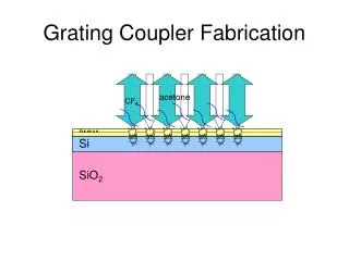
Fabrication Progress • Manufacturer: IHEP Experiment Factory. • The fabrication started in June 2010. • The work finished: • Parts machining; • Ceramic cold-shock test; • Copper plating & brazing test; • The work is being done: • Parts cleaning; • TIG welding; • Copper plating; • TiN coating; • Brazing;
Parts Machining – Doorknob • Finish machining; • Waiting for cleaning, TIG welding and brazing.
Parts Machining – Window • Finish machining; • Waiting for cleaning and brazing. Cold window parts Warm window parts
Parts Machining – Coaxial Finish Parts machining; Waiting for cleaning, TIG welding, copper plating and brazing.
Ceramic Brazing Brazing After ceramic brazing; Waiting for TiN coating, being brazed with other parts;
Ceramic Cold Shock Testing • The cold window works under 80K temperature, it is need to do cold shock test; • Test 99.5% and 97% alumina disk, 2 pieces for each; • The test procedure: • Cover the ceramic disks by Aluminium foil; • Put them in liquid Nitrogen; • After cooled down, take them out to room temperature; • Repeat for 3 times. • Uncover and watch it, make sure there is no crack. • No crack was noticed on all ceramic disks.
Ceramic Cold Shock Testing Ceramic cooled by liquid N2 Put ceramic in liquid N2 After taking them out
Bellow Plating And Brazing Test • We are poorly experienced in copper plating on bellow, so the plating and brazing test was necessary. The bellow before plating The bellow after plating
Bellow Plating Test – Detail There are some places missing plating There are some bubbles on small bellow surface after heat treatment in H2 furnace
Bellow Plating Test For the test result not good, the bellow was plated by another manufacturer; The new result looks good, but the copper volatilized in H2 furnace, we think the reason is the thickness is too small; The plating test will be tried again.
Bellow Brazing Test Brazing joint Use plated bellow for brazing test, there is no leak in brazing joint; The manufacturer want to use brazing in bellow connecting.
The Works Are Being Done • TIG welding – connecting flanges; • Copper plating – bellow, coaxial conductor, etc; • TiN coating – on ceramic surface; • Brazing – window and coaxial conductor; • The works above will be finished at the beginning of next year.
Summary • We confirmed the RF design and made the mechanical design, and have begun the fabrication; • The machining of coupler parts has been finished, and the technical test are being done ; • The coupler brazing and assembling will be completed at the beginning of next year.
THANK YOU 2010-12-7