Download
1 / 30
300 likes | 451 Vues
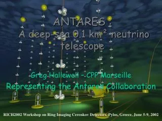
Status of the ANTARES Neutrino-Telescope. Alexander Kappes Physics Institute University Erlangen-Nuremberg for the ANTARES Collaboration. WIN´05, 6.–11. June 2005 Delphi, Greece. Introduction The ANTARES Detector First Results from Test-Lines Outlook.

E N D
Status of the ANTARES Neutrino-Telescope Alexander Kappes Physics Institute University Erlangen-Nuremberg for the ANTARES Collaboration WIN´05, 6.–11. June 2005 Delphi, Greece • Introduction • The ANTARES Detector • First Results from Test-Lines • Outlook
Supernova Remnant (RX J1713.7-3946) Gamma Ray Burst Active Galactic Nuclei Cosmic accelerators H.E.S.S. Hubble (Bepposax) 6. - 11. June 2005 WIN´05 Delphi, Greece
Detection of Cosmic Neutrinos Čerenkov light: Čerenkov angle: 42o wave lengths used: 350 – 500 nm Earth used as shield against all other particles A! X low cross section requires large detector volumes key reaction: + A! + X n Detector deployed in deep water / ice to reduce downgoing atmospheric muons 6. - 11. June 2005 WIN´05 Delphi, Greece
Physics with Neutrino Telescopes • Searching for point-like neutrino sources • Measurement of diffuse neutrino flux • Search for Dark Matter (WIMPs) • Search for exotic particles:e.g. magnetic monopoles 6. - 11. June 2005 WIN´05 Delphi, Greece
Mkn 421 Mkn 501 Mkn 501 Not seen Crab Crab VELA SS433 SS433 Not seen GX339-4 Galactic Center Why a Neutrino Telescope in the Mediterranean Sea? • Sky coverage complementary to telescopes at South Pole • Allows to observe the region of the Galactic Centre South Pole Mediterranean Sea Sources of VHE emission (HESS 2005) 6. - 11. June 2005 WIN´05 Delphi, Greece
The ANTARES Collaboration 20 institutions from 6 European countries 6. - 11. June 2005 WIN´05 Delphi, Greece
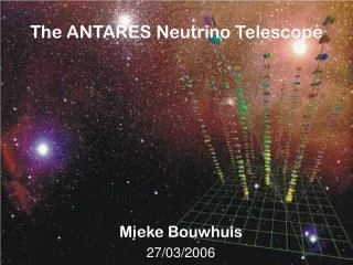
Buoy 460 m String Cable to Shore station Optical Module 14.5 m Junction Box Submersible 70 m The ANTARES Detector • Hostile environment: • pressure up to 240 bar • sea water (corrosion) artist´s view (not to scale) 6. - 11. June 2005 WIN´05 Delphi, Greece
One of 12 ANTARES Strings • Buoy • keeps string vertical (horizontal displacement < 20 m) • Storey • 3 optical modules (45o downwards) • electronics in titanium cylinder • EMC cable • copper wires + glass fibres • mechanical connection between storeys • Anchor • connector for cable to junction box • control electronics for string • dead weight • acoustic release mechanism 6. - 11. June 2005 WIN´05 Delphi, Greece
optical module B-screening Optical Module • Glass spheres: • material: borosilicate glass (free of 40K) • diameter: 43 cm; 1.5 cm thick • qualified for pressures up to 650 bar • Photomultipliers (PMT): • Ø 10 inch (Hamamatsu) • transfer time spread (TTS) = 1.3 ns • quantum efficiency: > 20% @ 1760 V (360 < < 460 nm) 6. - 11. June 2005 WIN´05 Delphi, Greece
Control room DAQ and Online Trigger • Data acquisition: • signals digitized in situ(either wave-form or single photo-electron (SPE)) • all data above low threshold (0.3 SPE)sent to shore • no hardware trigger • Online trigger: • computer farm at shore station (~100 PCs) • data rate from detector ~1GB/s(dominated by background) • trigger criteria: hit amplitudes, local coincidences, causality of hits • trigger output ~1MB/s = 30 TB/year Computer Centre 6. - 11. June 2005 WIN´05 Delphi, Greece
Online Trigger • Level 1: coincidences at one storey (Dt < 20 ns) or large individual signal (> 2.4 SPE) • Level 2:causality condition Dt < n / c· Dx • Level 3: accept if sufficiently many causally related hits exist Efficiency cos C = 1 / n Advanced algorithms under development 6. - 11. June 2005 WIN´05 Delphi, Greece
Calibration devices (Overview) • Time calibration system • 1 LED in each optical module • Optical beacons- LED beacons at 4 different storeys- Laser beacon at anchor • Acoustic positioning • receivers (hydrophones) at 5 storeys • 1 transceiver at anchor • autonomous transceivers on sea floor • Tiltmeter and compass at each storey 6. - 11. June 2005 WIN´05 Delphi, Greece
OM PMT Time-Calibration Systems • timing resolution of PMT signals determines pointing accuracylimited by intrinsic TTS of PMTs (1.3 ns))resolution of time calibration has to be better than 0.5 ns • expected variations of individual time offsets of PMT signals ~10 ns • complete calibration performed prior to deployment • two independent in situ calibration systems for PMTs available:Flashed LEDs in optical modules: • blue LED attached to back of each PMT • illuminates only local PMT Flashed optical beacons: • illuminate mainly PMTs on neighbouring strings • each beacon contains PMT for recording of emission time 6. - 11. June 2005 WIN´05 Delphi, Greece
Positioning System • motion of lines due to sea current (up to 30 cm/s) • 0.5 ns timing resolution requires 10 cm position accuracy for each PMT Acoustic system: • transmitter frequencies: 8–16 kHz (long distance) 40–60 kHz (short distance) • distance measurements via run time of acoustic signals • reconstruction of storey positions via triangulation Tiltmeters and compasses: • resolutions: tiltmeters = 0.2o , compasses = 1o System designed to provide PMT position accuracy better than 10 cm. 6. - 11. June 2005 WIN´05 Delphi, Greece
Environmental Parameters Continuously measured with various instruments on a dedicated string (Instrumentation Line) or at string anchors • quantities directly influencing reconstruction • attenuation length (25–60 m, depending on wave length and time)resolution ¼ 4 m • sound velocity ) acoustic positioning systemresolution = 0.1 m/s • other quantities measured • direction/speed of water current (via Doppler effect)precision: v = 0.5 cm/s, = 0.5o • temperature, salinity (via conductivity) • water pressure (device attached to anchor) 6. - 11. June 2005 WIN´05 Delphi, Greece
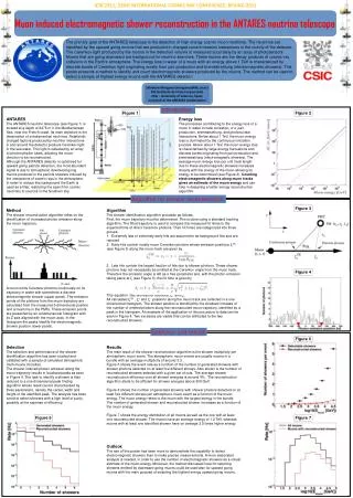
Muon Reconstruction Angular resolution (simulation) • E < 10 TeV: dominated by kinematics (Æ[,]) • E > 10 TeV: dominated by reconstruction accuracy • Energy resolution (simulation) • low E: muon track length • E > 1 TeV: Čerenkov light from radiative losses (small elm. showers) Muon momentum Dq < 0.3o (E > 10 TeV) D(log E) ¼ 0.3 (E > 1 TeV) 6. - 11. June 2005 WIN´05 Delphi, Greece
Detector Infrastructure and Prototype Lines • Deep-sea cable to shore station deployed • Junction box deployed and connected to deep-sea cable • Prototype lines deployed, connected to junction box and successfully recovered after 5 months 6. - 11. June 2005 WIN´05 Delphi, Greece
Baseline rate 0.4 seconds 3.5months Results from Prototype Lines (2003) • Long term measurements of optical background in the deep sea: • Technical problems: damaged optical fibre inside cable + water leak in electronics container ) no data with ns time resolution + loss of a storey 6. - 11. June 2005 WIN´05 Delphi, Greece
New Test-Lines: MILOM and Line0 Deployed March 2005, connected April 2005 Line0: full line without electronics (test of mechanical structure) MILOM:Mini Instrumentation Line with Optical Modules 6. - 11. June 2005 WIN´05 Delphi, Greece
MILOM setup Optical components: • equipped with final electronics • 3+1 optical modules at two storeys • timing calibration system: • two LED beacons at two storeys • Laser Beacon attached to anchor • acoustic positioning system: • receiver at 1 storey • transceiver (transmitter + receiver) at anchor allows to test all aspects of optical line Instrumentation components: • current profiler (ADCP) • sound velocimeter • water properties (CSTAR, CT) 6. - 11. June 2005 WIN´05 Delphi, Greece
First results from MILOM Timing calibration with LED beacons: • Measured relative offset of 3 optical modules on same storey • Large light pulses used ) TTS of PMT small Time difference between optical modules Optical beacon signal =0.75ns =0.68ns beacon signal Amplitude t OM1 – OM0 t OM2 – OM0 Time (ns) • electronics contribution to resolution around 0.5 ns • investigations in progress to separate various contributions 6. - 11. June 2005 WIN´05 Delphi, Greece
distribution around daily average distance from transponder (anchor) to receiver (first storey) vs. time 96.61 96.60 Distance (m) 96.59 96.58 8 6 4 2 0 2 4 6 8 2 4 6 8 10 12 14 16 18 20 Distance (mm) Time (day) First results from MILOM Acoustic positioning: • Several acoustic transponders installed • Currently only results from 1D measurements available Systematic effects under control on the level of 2 mm. 6. - 11. June 2005 WIN´05 Delphi, Greece
First Results from MILOM Compass headings from all three MILOM storeys: mostly synchronous movement of all storeys 6. - 11. June 2005 WIN´05 Delphi, Greece
First results from MILOM Environmental data: Water temperature + sound velocity Water temperature • Temperature almost constant at 13.2oC • Water temperature determines sound velocity (at given depth) Sound velocity Velocity (m/s) 6. - 11. June 2005 WIN´05 Delphi, Greece
First results from MILOM Environmental data: Sea current (current profiler) • Most times sea current < 15 cm/s • Significant changes of direction over periods from hours to days 6. - 11. June 2005 WIN´05 Delphi, Greece
First results from MILOM MILOM is a big success: • Data readout (waveforms + SPE) is working as expectedand yields ns timing information • In situ timing calibration and acoustic positioningreach expected resolution • All environmental sensors are working well • Continuous data from Slow Control (monitoring of various detector components) • Lots of environmental and PMT data available;intensive studies ongoing 6. - 11. June 2005 WIN´05 Delphi, Greece
Line0 • deployed to test mechanical structure • equipped with autonomous recording devices • water leak sensors • sensors connected to electrical and fibre loops for attenuation measurements • recovered in May 2005 Results: • no water leaks occurred • optical transmission losses at various points on fibresevidently all losses occur inside electronics container at entry and exit from cylinderpresently under intense investigations On first prototype strings fibres inside cables were damaged 6. - 11. June 2005 WIN´05 Delphi, Greece
ANTARES: further schedule • First full string (Line1) to be deployed and connected end of 2005 • Full detector installed in 2007 • From 2006 on: physics analysis ! 6. - 11. June 2005 WIN´05 Delphi, Greece
The future: KM3NeT • common effort of European n telescope groups(ANTARES, NEMO, NESTOR) + associated sciences • aim: build and operate a km3 neutrino telescope in the Mediterranean Sea • complementary to IceCube at the South Pole • expect to get EU funding (10 MEuro) for a design study (total budget 24 MEuro) by beginning of 2006 • Technical Design Report early 2009 km3 detectors required to exploit full physics potential of neutrino telescopes 6. - 11. June 2005 WIN´05 Delphi, Greece
Conclusions • MILOM proved to be a big success • data readout is working as expected • in situ timing and position resolution sufficient to reach angular resolution < 0.3o for neutrinos with E > 10 TeV • many more data to analyse • Line0 results • mechanical structure water tight and pressure resistant • optical losses in fibres currently under intense investigation • First full string expected to be deployed this year;Full detector in 2007 Well prepared for physics data to come in 2006 6. - 11. June 2005 WIN´05 Delphi, Greece