A Top-Level View of Computer Function and Interconnection
290 likes | 521 Vues
A Top-Level View of Computer Function and Interconnection. By Fernan Naderzad. Computer Components. Today we’ll go over: Von Neumann Architecture, Hardware and Software Approaches, Computer Functions, Interrupts, and Buses. Von Neumann Architecture.

A Top-Level View of Computer Function and Interconnection
E N D
Presentation Transcript
A Top-Level View of Computer Function and Interconnection By Fernan Naderzad
Computer Components • Today we’ll go over: Von Neumann Architecture, Hardware and Software Approaches, Computer Functions, Interrupts, and Buses.
Von Neumann Architecture • Data and Instructions are stored in a single read-write memory. • The contents of this memory are addressable by location, without regard to the type of data contained there. • Execution occurs in a sequential fashion (unless explicitly modified) from one instruction to the next.
More Components.. • I/O Components: a module that accepts data, and instructions and converts them into instruction signals usable by the system. It can also report results in the form of an output module. • Memory: A place to store instructions and data temporarily. (Von Neumann pointed out that the same memory could be used to store both instructions and data).
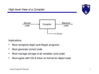
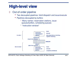
Computer Function • The basic function of a computer is to execute a program. • In its simplest form, instruction processing consists of two steps: The processor reads (fetches) instructions from memory one at a time and executes each instruction. • Processing required for a single instruction is called an instruction cycle. • The instruction cycle has two steps: the fetch cycle and the execute cycle.
Instruction Fetch and Execute The instruction is then loaded into a register known as the Instruction Register (IR).
Instruction Register • Processor-memory: Data may be transferred from processor to memory or from memory to processor. • Processor-I/O: Data may be transferred to or from a peripheral device by transferring between processor and I/O module. • Data-processing: Processor performs arithmetic or logic operations on data. • Control: An instruction may specify that the sequence of execution be altered.
Interrupts • A mechanism by which other modules may interrupt the normal processing of the processor. Classes of Interrupts • Program: Generated by some condition that occurs as a result of an instruction execution, such as arithmetic overflow, division by zero, attempt to execute an illegal machine instruction, or reference outside a user’s allowed memory space..
Interrupts (cont.) • Timer: Generated by a timer within the processor. This allows the operating system to perform certain functions on a regular basis. • I/O: Generated by an I/O controller, to signal normal completion of an operation or to signal a variety of error conditions. • Hardware Failure: Generated by failure such as power failure or memory parity error.
Interrupts.. Why bother? • They are provided as a way to improve processing efficiency! • For example.. Most external devices are much slower than the processor. Suppose the processor is transferring data to a printer using the instruction cycle. After each write operation, the processor must pause and remain idle until the printer catches up. The length of this pause may be on the order of hundred or even thousands of instruction cycles that do not involve memory. What a waste!
Interconnection Structures • So.. We have the components of a computer, but how are they connected? • The collection of paths connecting the various modules is called the interconnection structure. • Over the years, a number of interconnection structures have been tried. The most common is the bus and various multiple-bus structures.
Bus Interconnection • A bus is a communication pathway connecting two or more devices. It is a shared transmission medium. However, only one device can transmit successfully at a time. • A bus typically consists of multiple communication pathways, or lines. Each line is capable of transmitting signals representing binary 1 and binary 0. Eventually, a sequence of binary digits can be transmitted across a single line. Taken together, several lines of a bus can be used to transmit binary digits simultaneously. (EX: 8-bit unit of data can be transmitted over 8 bus lines.)
Bus Structure • A system bus consists from about 50 to hundreds of separate lines. Each line is assigned a particular meaning or function. • Although there are many different bus designs they can all be classified into three functional groups: data, address, and control lines.
Bus Structure (cont.) • Data Lines: provide a path for moving data among system modules. These lines are called the data bus. • Address Lines: designate the source or destination of the data on the data bus. • Control Lines: control the access to and the use of the data and address lines.
Bus Structures (cont.) Typical Control Lines: • Memory write: causes data on the bus to be written into the addressed location. • Memory read: causes data from the addressed location to be placed on the bus. • I/O write: causes data on the bus to be output to the addressed I/O port. • I/O read: causes data from the addressed I/O port to be placed on the bus. • Transfer ACK: indicates that data have been accepted from or placed on the bus. • Bus Request: indicates that a module needs to gain control of the bus. • Bus Grant: indicates that the requesting module has been granted control of the bus. • Interrupt Request: Indicates that an interrupt is pending. • Interrupt ACK: Acknowledges that the pending interrupt has been recognized. • Clock: Is used to synchronize operations • Reset: Initializes all modules
Multiple-Bus Hierarchies If a great number of devices are connected to the bus, performance will suffer because: • In general, the more devices attached to the bus, the greater the bus length and greater delay. • Bus may become a bottleneck as the aggregate data transfer demand approaches the capacity of the bus. So.. Because of this, it is important to have a hierarchy.
Elements of Bus Design • Bus Lines: two generic types (dedicated and multiplexed). • A dedicated bus line is permanently assigned either to one function or to a physical subset of computer components. (EX: Address and Data Lines)
Timing • Timing refers to the way in which events are coordinated on the bus. • Buses use either synchronous timing or asynchronous timing.
Synchronous Timing • With synchronous timing, the occurrence of events on the bus is determined by a clock.
Asynchronous Timing • With asynchronous timing, the occurrence of one event on a bus follows and depends on the occurrence of a previous event.
PCI • Peripheral component interconnect (PCI) is a popular high-bandwidth, processor-independent bus. • Intel began work on PCI in 1990 for its Pentium-based systems. Intel soon released all patents to the public domain and promoted the creation of an industry association, the PCI Special Interest Group.
Bus Structure of PCI • PCI may be configured as a 32 or 64-bit bus. There are 49 mandatory signal lines for the PCI and are divided into groups. • System pins: Include the clock and reset pins. • Address and data pins: Include 32 lines that are time multiplexed for addresses and data. • Interface control pins: Control the timing of transactions and provide coordination among initiators and targets. • Arbitration pins: Unlike the other PCI signal lines, these are not shared. • Error reporting pins: Used to report parity and other errors • Interrupt pins: These are provided for PCI devices that must generate requests for service. • Cache support pins: These pins are needed to support a memory on PCI that can be cached in the processor or another device. • 64-bit bus extension pins: Include 32 lines that are time multiplexed for addresses and data that are combined with the mandatory address/data lines to form a 64-bit address/data bus. • JTAG/boundary scan pins: These signal lines support testing procedures defined in IEEE Standard 1149.1
Resources • Computer Organization and Architecture: Designing for Performance, 8th Edition By William Stallings, Prentice Hall; ISBN-10: 0-13-607373-5 • “Computer Buses” Harries, Ian. http://www.doc.ic.ac.uk/~ih/teaching/lectures/comparch/bus/ • “Module 2: Top-Level View of Computer Organization” Nguyen Thi Hoang Lan. http://cnx.org/content/m29708/latest/