Download
1 / 23
240 likes | 269 Vues
Dive into the world of lenses and optical systems, from basic terminology to lens equations and image formation through ray diagrams in Chapter 5’s Geometrical Optics. Understand the principles of refraction at spherical surfaces and the significance of thin lenses. Master lens maker’s equation, optical centers, focal planes, and more.

E N D
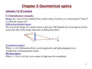
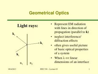
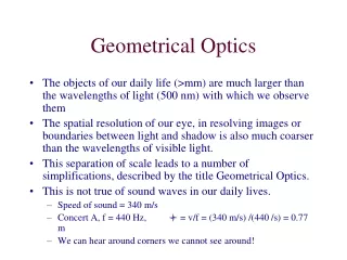
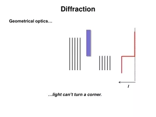
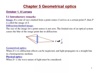
Chapter 5 Geometrical optics October 1, 8 Lenses 5.1 Introductory remarks Image:If a cone of rays emitted from a point source S arrives at a certain point P, then P is called the image of S. Diffraction-limited image:The size of the image for a point source is not zero. The limited size of an optical system causes the blur of the image point due to diffraction: Geometrical optics:When D >>l, diffraction effects can be neglected, and light propagates in a straight line in a homogeneous medium. Physical optics:When D ~l, the wave nature of light must be considered.
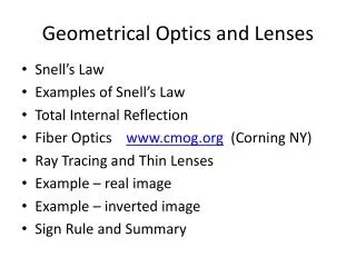
5.2 Lenses Lens:A refracting device that causes each diverging wavelet from an object to converge or diverge to form the image of the object. • Lens terminology: • Convex lens, converging lens, positive lens • Concave lens, diverging lens, negative lens • Focal points • Real image: Rays converge to the image point • Virtual image: Rays diverge from the image point • Real object: Rays diverge from the object point • Virtual object: Rays converge to the object. S P P S S P
y A(x,y) D x F d 5.2.1 Aspherical surfaces Determining the shape of the surface of a lens: The optical path length (OPL) from the source to the output wavefront should be a constant. Example: Collimating a point source (image at infinity) The surface is a hyperboloid when nti>1, and is an ellipsoid when nti<1. nt ni Example: Imaging a point source. The surface is a Cartesian oval. Aspherical lenscan form a perfect image, but is hard to manufacture. Spherical lenscannot form a perfect image (aberration), but is easy to manufacture.
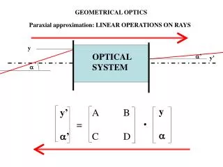
A qi lo li qt R j P S V C so si n2 n1 5.2.2 Refraction at spherical surfaces Terminology: vertex, object distance so, image distance si, optical axis. Gaussian (paraxial, first-order) optics: When j is small, cosj≈1, sinj ≈j, Paraxial imaging from one spherical surface:
Paraxial imaging from a single spherical surface: Note: 1) This is the grandfather equation of many other equations in geometrical optics. 2) For a planar surface (fish in water): (A bear needs to know this.) 3) Magnification: (P5.6).
Fo Fi fi Fi C V fo si Fo C V so Example 5.2 Object (first) focal length: when si = , Image (second) focal length: when so = , Virtual image (si< 0) and virtual object (so< 0): EVERYTHING HAS A SIGN! Sign convention for lenses(light comes from the left): • so, fo + left of vertex • si, fi+ right of vertex • xo + left of Fo • xi + right of Fi • R + curved toward left • yo, yi + above axis
Read: Ch5: 1-2 Homework: Ch5: 1,5,6 Note: In P5.1 the expression should be (so+si-x)2. Due: October 10
nm R1 R2 P P' V1 V2 2nd surface 1st surface C2 C1 S nl S P' P so1 (R1, nm, nl) (R2, nl, nm) si1 d si2 so2 October 10,15 Thin lenses 5.2.3 Thin lenses Thin lens: The lens thickness is negligible compared to object distance and image distance. Thin lens equations: Forming an image with two spherical surfaces:
If the lens is thin enough, d /si1→ 0.Assuming nm=1, we have the thin lens equation: Lens maker’s equation: Remember them together with the sign convention. Gaussian lens formula: Question: what if the lens is in water?
A C2 C1 O B R1 R2 Optical center:All rays whose emerging directions are parallel to their incident directions pass through one special common point inside the lens. This point is called the optical center of the lens. Proof: Conversely, rays passing through O refract parallelly. Proof: • For a thin lens, rays passing through the optical center are straight rays. Corollary: For a thin lens, with respect to the optical center, the angle subtended by the image equals the angle subtended by the object.
C’ C Focal plane C P S Fi Focal plane Focal plane: A plane that contains the focal point and is perpendicular to the optical axis. In paraxial optics, a lens focuses any bundle of parallel rays entering in a narrow cone onto a point on the focal plane. Proof: 1st surface, 2nd surface Image plane Image plane:In paraxial optics, the image formed by a lens of a small planar object normal to the optical axis will also be a small plane normal to that axis.
Read: Ch5: 2 Homework: Ch5: 7,10,11,15(Optional),21 Due: October 19
2 S' A yo 1 P Fi Fo O S 3 yi B P' xi f xo f si so October 17 Ray diagrams Finding an image using ray diagrams: Three key rays in locating an image point: • Ray through the optical center: a straight line. • Ray parallel to the optical axis: emerging passing through the focal point. • Ray passing through the focal point: emerging parallel to the optical axis. Newtonian lens equation: Meanings of the signs: + – • so Real object Virtual object • siReal image Virtual image • f Converging Diverging lens • yo Erect object Inverted object • yiErect image Inverted image • MTErect image Inverted image Transverse magnification: Longitudinal magnification: Example 5.3
4 Fi1 Fi2 O1 O2 Fo2 Fo1 d<f1, d<f2 so2 d si1 • Thin lens combinations • I. Locating the final image of L1+L2 using ray diagrams: • Constructing the image formed by L1 as if there were no L2. • Using the image by L1 as an object (may be virtual), locating the final image. The ray through O2 (Ray 4, may be backward) is needed. II. Analytical calculation of the image position: si2 is a function of (so1, f1, f2, d) Total transverse magnification:
Back focal length (b.f.l.): Distance from the last surface to the 2nd focal point of the system. Front focal length (f.f.l.): Distance from the first surface to the 1st focal point of the system. Special cases: 1) d = f1+f2: Both f.f.l. and b.f.l. are infinity. Plane wave in, plane wave out (telescope). 2) d → 0: effective focal length f: 3) N lenses in contact: Example 5.5
Reading: Astronomical telescope − infinite conjugate: (d = f1+f2) Angular magnification: a2 a1 f2 f1
Read: Ch5: 2 Homework: Ch5: 22,32,33,42(Optional),43 Due: October 26
y x October 19 Mirrors and prisms 5.4 Mirrors 5.4.1 Planar mirrors • |so|=|si|. • Sign convention for mirrors: so and si are positive when they lie to the left of the vertex. • Image inversion (left hand right hand). 5.4.3 Spherical mirrors The paraxial region (y<<R): R
A qi qf S F C V P f si R 2 S so 4 1 3 F V C P The mirror formula: Finding an image using ray diagrams: Fourkey rays in finding an image point: • Ray through the center of curvature. • Ray parallel to the optical axis. • Ray through the focal point. • Ray pointing to the vertex. Transverse magnification: Example 5.10
a d qt2 qi2 qi1 qt1 • 5.5 Prisms • Functions of prisms: • Dispersion devices. • Changing the direction of a light beam. • Changing the orientation of an image. • 5.5.1 Dispersion prisms • Apex angle, angular deviation
Minimum deviation: The minimum deviation ray traverses the prism symmetrically. At minimum deviation, This is an accurate method for measuring the refractive indexes of substances.
Read: Ch5: 3-5 Homework: Ch5: 73,81,82,85,86(Optional),88,89 Due: October 26
You don’t make a discovery if you didn’t guess it wrong. Pengqian Wang