Download
1 / 90
900 likes | 935 Vues
Learn about the Brayton Cycle for airbreathing and combustion steps in high-speed propulsion systems, with a focus on the reduction of oxidizer requirements and enhanced operational envelopes. Discover the advantages, such as decreased weight, wider landing options, and expanded launch windows. Explore the thermodynamic efficiency of the Ideal Ramjet and its impact on engine performance.

E N D
• Oxidizer … “liquid air” Have to take our own along So that the engine can breathe At high altitudes • How Much Oxidizer? … depending op chosen propellants … 4-9 times as much As the fuel we carry!
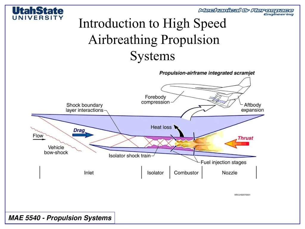
Flight Without Oxidizer, I What if we could get enough oxygen from ambient air? X-43 airbreathing SCRAMjet engine What happens to our Isp? OK .. Lets loose the Oxidizer … and our Isp goes up by a factor Of 7! … but where do we the the Oxidizer for combustion? ….
… from the atmosphere
Flight Without Oxidizer, II Do Not Need Oxidizer here For a large portion of the Launch trajectory there is Plenty Enough air For combustion if you are going fast enough Need Oxidizer here
Fuel Efficiencies of Various High Speed Propulsion Systems Isp Minimal turbo-machinery
Operations Payoffs for Airbreathing Launch • Decreased gross lift-off weight, resulting in smaller facilities and easier handling • Wider range of emergency landing sites for intact abort • Powered flyback/go-around & more margin at reduced power • Self-ferry & taxi capabilities • Greatly expanded launch windows (double or triple) • Rapid orbital rendezvous (up to three times faster than rockets) • Wider array of landing sites from orbit, with 2,000-mile cross range and increased range • Reduced sensitivity to weight growth
Our total launch mass goes from 10,000 kg/kg down to <1400 kg/kg wow!
Squeeze Bang Blow Suck Airbreathing Propulsion Basics
Brayton Cycle for Airbreathing Combustion Step Process 1) Intake (suck) Isentropic Compression 2) Compress the Air (squeeze) Adiabatic Compression 3) Add heat (bang) Constant Pressure Combustion 4) Extract work (blow) Isentropic Expansion in Nozzle 5) Exhaust Heat extraction by surroundings … step 5 above happens In the exhaust plume and has minimal Effect on engine performance Step 3 Step 1-2 Step 4 Step 5 (Credit Narayanan Komerath, Georgia Tech)
Brayton Cycle for Airbreathing Combustion (cont’d) • Ramjet Engine Combustion Cycle Steps • Compression and Power extraction steps Performed passively (Credit Narayanan Komerath, Georgia Tech) Step 1-2 Step 3 Step 4
Turbine Combustor Nozzle Compressor Turbojet Afterburner Turbine Compressor Afterburner Turbofan Combustor Nozzle Fan Brayton Cycle for Airbreathing Combustion (cont’d) • Turbojet/Turbo fan engines Combustion Cycle steps Compression and Power extraction steps use Turbo-machinery To augment cycle Inlet Inlet
Ideal Ramjet Cycle Analysis Step 1-2 Step 3 Step 4
Ideal Ramjet Cycle Analysis T-s Diagram Step 1-2 Step 3 Step 4 T s
Thermodynamic Efficiency of Ideal Ramjet • Net Work Available --> work perform by system in step 4 minus work required for step 1-2 • Net heat input --> heat input during step 3 (combustion) - heat lost in exhaust plume (Credit Narayanan Komerath, Georgia Tech) Step 1-2 Step 3 Step 4
Thermodynamic Efficiency of Ideal Ramjet (cont’d) • Ideal Cycle Efficiency() = (Net work output)/(Net heat input} (Credit Narayanan Komerath, Georgia Tech) Step 1-2 Step 3 Step 4
Thermodynamic Efficiency of Ideal Ramjet (cont’d) • Ideal Cycle Efficiency = (Net work output)/(Net heat input} (Credit Narayanan Komerath, Georgia Tech) Step 1-2 Step 3 Step 4
Thermodynamic Efficiency of Ideal Ramjet (cont’d) • Assume … Cpair ~ Cpproducts (Credit Narayanan Komerath, Georgia Tech) Step 1-2 Step 3 Step 4
Thermodynamic Efficiency of Ideal Ramjet (cont’d) • For simplicity … let … Cpair ~ Cpproducts
Thermodynamic Efficiency of Ideal Ramjet (cont’d) • From C-->D flow is isentropic … (Credit Narayanan Komerath, Georgia Tech) Step 1-2 Step 3 Step 4
Thermodynamic Efficiency of Ideal Ramjet (cont’d) • Adiabatic compression across diffuser (Credit Narayanan Komerath, Georgia Tech) Step 1-2 Step 3 Step 4
Thermodynamic Efficiency of Ideal Ramjet (cont’d) • Sub into efficiency equation (Credit Narayanan Komerath, Georgia Tech) Step 1-2 Step 3 Step 4
Thermodynamic Efficiency of Ideal Ramjet (cont’d) (Credit Narayanan Komerath, Georgia Tech) Step 1-2 Step 3 Step 4
Thermodynamic Efficiency of Ideal Ramjet (cont’d) (Credit Narayanan Komerath, Georgia Tech) Step 1-2 Step 3 Step 4 As engine pressure ratio, PB/PA, goes up … h goes up As combustor temperature difference TC-TB goes up … h goes up iii) As inlet total pressure ratio (P0B/P0A) goes down … (stagnation pressure loss goes up) … h goes down
Why is total pressure recovery important? • Choked Nozzle Throat massflow • Thrust is proportional to engine massflow
Ideal Ramjet: Inlet and Diffuser • Take a Rocket motor and “lop the top off” • Works Ok for subsonic, but for supersonic flow … can’t cram enough air down the tube • Result is a normal shock wave at the inlet lip
Ideal Ramjet: Inlet and Diffuser (cont’d) M M • Mechanical Energy is Dissipated into Heat • Huge Loss in Momentum
Ideal Ramjet: Inlet and Diffuser (cont’d) • So … we put a spike in front of the inlet • How does this spike Help? • By forming an Oblique Shock wave ahead of the inlet
Oblique Shockwave Theory Background Anderson, Compressible Flow, Chapter 4 pp.127-145 • In Supersonic flow, pressure disturbances cannot outrun “point-mass” generating object • Result is an infinitesimally weak “mach wave”
Oblique Shock Wave (cont’d) • When generating object is larger than a “point”, shockwave is stronger than mach wave …. Oblique shock wave b>m • b -- shock angle • q -- turning or “wedge angle” q
Oblique Shock Wave Geometry • Must satisfy i) continuity ii) momentum iii) energy Tangential Normal Ahead w1, Mt1 u1, Mn1 Of Shock Behind w2, Mt2 u2, Mn2 Shock
Collected Oblique Shock Equations • Continuity • Momentum • Energy
Oblique Shock Waves:Collected Algorithm • Properties across Oblique Shock wave ~ f(M1, b) • q is the geometric angle that “forces” the flow
Oblique Shock Waves:Collected Algorithm (cont’d) • Can be re-written as third order polynomial in tan(q) • “Very Easy” numerical solution • Cubic equation has three solutions i) weak shock ii) Strong shock iii) non-physical solution
Oblique Shock Waves:Collected Algorithm (cont’d) • “Less Obvious” explicit solution = 0 ---> Strong Shock = 1 ---> Weak Shock
Oblique Shock Waves:Collected Algorithm (cont’d) • ... and the rest of the story …
Oblique Shock Waves:Collected Algorithm (concluded) • ... and the rest of the story …
Basic Oblique Shock Example: •M1 = 3.0, p1=1atm, T1=288K, q=20 g=1.4, • Compute shock wave angle (weak) • Compute P02, T02, p2, T2, M2 … Behind Shockwave
Basic Oblique Shock Example : (cont’d) •M1 = 3.0, p1=1atm, g=1.4, T1=288K, q=20 • Explicit Solver for b =7.13226 =0.93825
Basic Oblique Shock Example : (cont’d) •M1 = 3.0, p1=1atm, g=1.4, T1=288K, q=20 • d= 1 (weak shock) = 37.764
Basic Oblique Shock Example : (cont’d) •M1 = 3.0, p1=1atm, g=1.4, T1=288K, q=20 • Normal Component of Free stream mach Number =1.837 • Compute Pressure ratio across shock Normal Shock Solver p2 = 3.771(1 atm) = 3.771 atm • Flow is compressed
Basic Oblique Shock Example : (cont’d) •M1 = 3.0, p1=1atm, g=1.4, T1=288K, q=20 • Temperature ratio Across Shock Normal Shock Solver T2 = 1.5596(288 K) = 449.2 K
Basic Oblique Shock Example : (cont’d) •M1 = 3.0, p1=1atm, g=1.4, T1=288K, q=20 • Stagnation Pressure ratio across shock =1.837 Normal Shock Solver 0.7961
Basic Oblique Shock Example : (cont’d) •M1 = 3.0, p1=1atm, g=1.4, T1=288K, q=20 • Stagnation Pressure ratio (alternate method) =0.7961
Basic Oblique Shock Example : (cont’d) •M1 = 3.0, p1=1atm, g=1.4, T1=288K, q=20 • Stagnation Pressure =29.24 atm
Basic Oblique Shock Example : (cont’d) •M1 = 3.0, p1=1atm, g=1.4, T1=288K, q=20 • Stagnation Temperature behind shock =806.4 oK
2-D Ramjet Inlet Example P0B M1=4.0 B • Compare MB and P0 behind normal shockwaves b= 40 B P0B Assume g=1.4
2-D Ramjet Inlet Example (cont’d) P0B M1=4.0 B • From Normal Shock wave solver