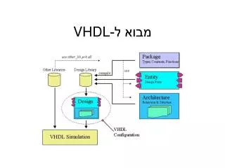
5. VHDL 을 이용한 조합논리회로 설계
5. VHDL 을 이용한 조합논리회로 설계. 1. VHDL 의 설계 기초. 1.1 기본 논리 게이트를 이용한 VHDL 설계 조합논리 : 0 과 1 로 표시되는 논리 대수를 이용해 필요한 회로를 구성 입력신호에 의해 단순히 출력으로 연산된 결과가 나타나는 디지털 회로의 가장 기본적인 회로 기본 논리 게이트 : NOT, AND, OR 1 AND 게이트 설계 AND gate 동작 설명. AND gate 를 위한 VHDL AND gate 의 entity 기술

5. VHDL 을 이용한 조합논리회로 설계
E N D
Presentation Transcript
1. VHDL의 설계 기초 1.1 기본 논리 게이트를 이용한 VHDL 설계 • 조합논리: 0과 1로 표시되는 논리 대수를 이용해 필요한 회로를 구성 • 입력신호에 의해 단순히 출력으로 연산된 결과가 나타나는 디지털 회로의 가장 기본적인 회로 • 기본 논리게이트 : NOT, AND, OR 1 AND 게이트설계 • AND gate 동작 설명
AND gate를 위한 VHDL • AND gate의 entity 기술 그림 5.2 AND gate의 인터페이스
AND gate entity의 VHDL 코드 entity AND_gate is port( pin_A, pin_B : in bit; --입력인터페이스 정의 pin_F: out bit); --출력인터페이스 정의 end AND_gate; • AND gate의 아키텍처 기술 • 동작적 모델링 • AND gate 아키텍처의 VHDL 코드: 동작적 모델링 --조건문 이용 architecturebeh of AND_gate is begin process( pin_A, pin_B) begin --AND gate의 동작을 기술 ifpin_A = ‘1’ and pin_B = ‘1’ then pin_F <= ‘1’; else pin_F <= ‘0’; end if; end process; end beh;
--신호할당문 이용 architecturebeh_ex2 of AND_gate is begin process (pin_a, pin_B) begin pin_F <= pin_A and pin_B; --연산자 “and”를이용 end process; end beh_ex2; • 자료흐름적모델링 • 실제 신호의 흐름을 연산자나 병행신호 또는 조건적 병행 신호, 선택적 병행 신호 할당문을 이용하여 기술. • AND gate의 아키텍처의 VHDL 코드:자료 흐름적 모델링 --병행신호 할당문을 이용한 자료 흐름적 모델링 architecture DataFlow_ex1 of AND_gate is begin pin_F <= pin_A and pin_B ; --연산자 “and”를이용 end DataFlow_ex1; --조건적병행 신호 할당문을 이용한 자료 흐름적 모델링 architectureDataFlow_ex2 of AND_gate is begin pin_F <=‘1’ when pin_A=‘1’ and pin_B=‘1’ else 0; --조건적병행문 end DataFlow_ex2;
AND gate의 시뮬레이션 결과 그림 5.3 AND gate의 시뮬레이션 결과 • configuration을 이용한 AND gate의 연결 • 하나의 엔티티에 여러 개의 아키텍처를 갖도록 설계하여 시뮬레이션 과정에서 필요한 아키텍처를 엔티티와 연결하도록 기술하는 것이 효율적일 경우가 있다.
그림 5.3 configuration을 이용한 AND gate의 연결 • AND gate의 configurationVHDL 코드 --configuration 사용 configurationconnect_entity of AND_gate is for beh_ex1 --구성할아키텍처 이름을 적는다 -- 특별한 구성형태가 없으므로 가장 간단한 형대의 구성이다 end for; end connect_entity;
AND gate의 VHDL 코드:전체 코드 libraryIEEE; use IEEE.std_logic_1164.all entity AND_gate is port( pin_A, pin_B : in bit; pin_C :out bit); end AND_gate; --조건문을이용 architecturebeh_ex1 of AND gate is begin process(pin_A, pin_B) begin if pin_A=‘1’ and pin_B=‘1’ then pin_F <= ‘1’; else pin_F <= ‘0’; end if; end process; end beh_ex1; --신호할당문을이용 architecturebeh_ex2 of AND_gate is begin process(pin_A, pin_B) begin pin_F <= pin_A and pin_B; end process; end beh_ex2;
--병행신호 할당문을 이용 architecturedataflow_ex1 of AND_gate is begin pin_F <= pin_A and pin_B; end dataflow_ex1; --조건적병행신호 할당문을 이용 architecturedataflow_ex2 of AND_gate is begin pin_F <= ‘1’ when pin_A =‘1’ and pin_B = ‘1’ else ‘0’ --조건적병행신호문 end dataflow_ex2; --configuration 사용 configurationconnect_entity of AND gate is for beh_ex1 end for; end connect_entity;
2. XNOR gate (exclusive NOR) 설계 • XNOR 게이트의동작 그림 5.5 XNOR gate.
XNOR gate를 위한 VHDL • XNOR gate의 엔티티 기술 • XNOR gate엔티티의VHDL 코드 entity XNOR_gate is port (pin_A, pin_B: in bit; pin_F:out bit); end XNOR_gate; • XNOR gate의 architecture 기술:동작적모델링 --조건문을 이용 architecturebeh_mod of XNOR gate is begin process( pin_A, pin_B) begin if (pin_A = pin_B) then pin_F <= ‘1’; else pin_F <= 0; end if end process; end beh_mod;
XNOR gate 아키텍처 기술:자료흐름적 모델링 architectureDF_mod of XNOR_gate is begin pin_F <= not (pin_Axnorpin_B); end DF_mod; • XNOR gate의 시뮬레이션 결과 그림 5.6 XNOR gate의 시뮬레이션 결과.
그림 5.7 XNOR의 등가회로 그림 5.8 내부 신호선들에 의한 각 게이트의 연결
자료흐름적 모델링 • XNOR gate의 VHDL 코드 --병행신호 할당문을 이용한 자료흐름적 모델링 libraryIEEE; use IEEE.std_logic_1164.all; entity XNOR_gate is port(pin_A, pin_B: in bit; pin_F : out bit); end XNOR_gate; architecture DataFlow of XNOR_gate is --내부신호들의 선언 signal sig_A, sig_B, sig_C, sig_D :bit; begin sig_A <= not pin_A; sig_B <= not pin_B; sig_C <= pin_A and pin_B; sig_D <= sig_A and sig_B; pin_F <= sig_C or sig_D; end DataFlow;
XNOR gate의 아키텍처의 VHDL 코드 --병행 신호할당문을이용한 자료흐름적 모델링 libraryIEEE; use IEEE.std_logic_1164.all; entity XNOR_gate is port( pin_A, pin_B : in bit; pin_F : out bit); end XNOR_gate; architecture DataFlow of XNOR_gate is begin pin_F <= ((not pin_A) and (not pin_B)) or (pin_A and pin_B); end DataFlow;
동작적모델링 • 프로세스를 이용해 XNOR gate 기술 그림 5.10 프로세스 문을 이용한 XNOR gate.
XNOR gate의 VHDL코드 (동작적 모델링) --프로세스 문을 이용한 동작적 모델링 library IEEE; use IEEE.std_logic_1164.all; entity XNOR_gate is port( pin_A, pin_B : in bit; pin_F : out bit); end XNOR_gate; architecture beh of XNOR_gate is signal sig_C, sig_D : bit; begin P1:process(pin_A, pin_B) begin sig_C <= pin_A and pin_B; end process P1; P2: process (pin_A, pin_B) variable sig_A, sig_B : bit; -- 프로세스 내의 선언은 신호를 사용 못함 begin sig_A := not pin_A; sig_B := not pn_B; sig_D <= sig_A and sig_B; end process P2; P3: process (sig_C, sig_D) begin pin_F <= sig_C or sig_D; end process P3; end beh;
구조적 모델링 • 컴포넌트를 이용한 XNOR gate의 설계 • 각 게이트를 컴포넌트로 표현 그림 5.11 컴포넌트를 이용한 XNOR gate의 설계
XNOR gate의 VHDL 코드:컴포넌트 이용 library ieee; use ieee.std_logic_1164.all; entity XNOR_gate is port(pin_A, pin_B: in bit; pin_F: out bit); end XNOR_gate; architecture exm_model of XNOR_gate is component gate_A port( in_A, in_B: in bit; out_F : out bit); end component; component gate_O port(in_A, in_B : in bit; out_F : out bit); end component; component gate_NA port(in_A, in_B : in bit; out_F : out bit); end component;
signal sig_C, sig_D: bit; begin --위치결합에 의한 가시화 --U1 : gate_A port map (pin_A, pin_B, sig_C); --U2 : gate_NA port map (pin_A, pin_B, sig_D); --U3 : gate_O port map (sig_C, sig_D, pin_F); --이름 결합에 의한 가시화 U1: gate_A port map (in_A => pin_A, in_B => pin_B, out_F => sig_C); U2: gate_NA port map (in_A => pin_A, in_B =>pin_B, out_F =>sig_D); U3: gate_O port map (in_A => sig_C, in_B => sig_D, out_F => pin_F); end exm_model;
설계 엔티티를 이용한 XNOR gate의 설계 • XNOR gate의 VHDL 코드:설계 엔티티를 이용 library ieee; use ieee.std_logic_1164.all; entity XNOR_gate_des is port( pin_A, pin_B : in bit; pin_F : out bit); end XNOR_gate_des; architecture exm_model of XNOR_gate_des is signal sig_C, sig_D :bit; begin E1: entity work.gate_A (exm_model) port map (in_A => pin_A, in_B => pin_B, out_F => sig_C); E2: entity work.Gate_NA(exm_model) port map (in_A => pin_A, in_B => pin_B, out_F => sig_D); E3: entity work.Gate_O (exm_model) port map (in_A => sig_C, in_B => sig_D, out_F => pin_F); end exm_model;
package를이용한 XNOR gate 설계 • AND, OR, NOT-AND gate를 패키지 내에서 선언 후 패키지를 이용한 XNOR gate 설계 • 설계한 각 게이트를 컴포넌트로 선언, 저장 후 컴파일하여package_for_xnor를 생성 • XNOR gate의 VHDL 코드:패키지 작성 libraryieee; use ieee.std_logic_1164.all; package package_for_xnor is component gate_A port(in_A, in_B: in bit; out_F : out bit); end component; component gate_O port(in_A, in_B : in bit; out_F:out bit); end conponent; component gate_NA port(in_A, in_B: in bit; out_F:out bit); end component; end prockage_for_xnor;
XNOR gate의 VHDL 코드: 패키지를 이용 library ieee; use ieee.std_logic_1164.all use work.package_for_xnor.all; entity XNOR_gate_pac is port(pin_A, pin_B: in bit; pin_F :out bit); end XNOR_gate_pac; architecture exm of XNOR_gate_pac is signal sig_C, sig_D : bit; begin U1: gate_A port map (in_A =>pin_A, in_B=>pin_B, out_F=>sig_C); U2: gate_NA port map(in_A =>pin_A, in_B =>pin_B, out_F =>sig_D); U3 gate_O port map(in_A => sig_C, in_B => sig_D, out_F=>pin_F); end exm;
1.2 간단한조합논리회로를 이용한 설계 1. 연산자를 이용한 조합논리회로 설계 • 논리 연산자를 이용한 설계 • AND, OR, NOT, XOR, NOR… 등의 연산자를 이용한 논리회로 설계 그림 5.12 논리연산자를 위한 조합논리회로의 구현.
그림 5.13 엔티티와 내부 신호선을 정의. • 엔티티 이름 : logic_gate • 입출력: pin_A, pin_B, pin_C, pin_D, 및 pin_F로정의됨 (port) • 신호선:sig_A, sig_B, sig_C, sig_D로 정의하여 사용.
연산자를이용한 조합논리회로 설계 libraryieee; use IEEE.std_logic_1164.all; entity logic_gate is port( pin_A, pin_B, pin_C, pin_D : in std_logic; pin_F : out std_logic); end logic_gate; architecture arc of logic_gate is signal sig_A, sig_B, sig_C, sig_D: std_logic; begin sig_A <= pin_A and pin_B; sig_B <= pin_A nor pin_C; sig_C <= pin_B or pin_D; sig_D <= sig_Bnandsig_C; pin_F <= sig_Axorsig_D; end arc;
관계 연산자를 이용한 설계 그림 5.15 관계연산자를 이용한 조합논리회로 설계. • 관계 연산자를 이용한 조합논리회로의 설계: 예제 1 libraryieee; use leee.std_logic_1164.all; entity relational_gate is port( pin_A, pin_B : in bit_vector (3 downto 1); pin_F:outboolean); end relational_gate; architecture arc of relational_gate is begin pin_F <= (pin_A = pin_B); end arc;
관계 연산자를 이용한 조합논리회로의 설계: 예제 2 library ieee; use ieee.std_logic_1164.all; entity realtional_gate_ex2 is port( pin_A, pin_B : in bit_vector (3 downto 1); pin_F:out bit); end relational_gate_ex2; architecture arc of relational_gate_ex2 is signal sig_A, sig_B, sig_C : bit; begin sig_A <= (pin_A(3) = pin_B(3)); sig_B <= (pin_A(2) = pin_B(2)); sig_C <= (pin_A(1) = pin_B(1)); pin_F <= ((sig_A = sig_B) = sig_C); end arc;
산술연산자를 이용한 설계 • 산술연산자를 이용할 경우에는 “ieee.std_logic_unsigned” 포함시켜야한다. 그림 5.17 산술연산자를 위한 블록도.
산술연산자를 이용한 설계 libraryieee; use ieee.std_logic_1164.all; use ieee.std_logic_arith.all; --산술연산에필요한 패키지 (라이브러리) entity arith_gate is port( pin_A, pin_B : in std_logic_vector (3 downto 0); pin_AD: out std_logic_vector (4 downto 0); pin_SB: out std_logic_vector (3 downto 0); pin_MT: out std_logic_vector (7 downto 0)); end arith_gate; architecture arc of arith_gate is begin pin_AD <= (‘0’ & pin_A ) + ( ‘0’ & pin_B); pin_SB <= pin_A - pin_B; pin_MT <= pin_A * pin_B; end arc;
2. 조건 기능을 이용한 조합논리회로 설계 • 조건적 병행신호 할당문을 이용한 설계 그림 5.19 조건적 병행신호 할당문을 이용한 설계 • 조건적 병행신호 할당문을 이용한 설계 1 libraryieee; use ieee.std_logic_1164.all; entity cond_logic is port(pin_A, pin_B, pin_S : in std_logic; pin_F :out std_logic); end cond_logic; architecture arc of cond_logic is begin pin_F <= pin_A when pin_S = ‘1’ else pin_B; end arc;
조건적병행신호 할당문을 이용한 설계-2 library ieee; use ieee.std_logic_1164.all; entity cond_logic_2 is port( pin_A, pin_B, pin_C : in std_logic; pin_S1, pin_S2 : in std_logic; pin_F :out std_logic); end cond_logic_2; architecture arc of cond_logic_2 begin pin_F <= pin_C when (pin_S2= ‘1’ and pin_S1 = ‘1’) else pin_B when (pin_S2= ‘1’ and pin_S1 = ‘0’) else pin_A when (pin_S2= ‘0’ and pin_S1 = ‘1’) else ‘0’; end arc;
선택적병행 신호 할당문을 이용한 설계 그림 5.22 선택적 병행신호 할당문을 이용한 조합논리회로 설계.
선택적병행 신호 할당문을 이용한 설계 libraryieee; use ieee.std_logic_1164.all; entity with_logic is port(pin_A, pin_B, pin_C, pin_D : in std_logic; pin_S : in std_logic_vector (1 downto 0); pin_F : out std_logic); end with_logic; architecture arc of with_logic is begin with pin_S select pin_F <= pin_A when “00”, pin_B when “01”, pin_C when “10”, pin_D when others; end arc;
IF문을 이용한 설계 그림 5.24 IF 문을 이용한 조합논리회로 설계 회로도.
IF문을 이용한 설계 libraryieee; use ieee.std_logic_1164.all; entity if_logic is port(pin_A, pin_B, pin_C : in std_logic; pin_S0, pin_S1:in std_logic; pin_F : out std_logic); end if_logic; architecture arc of if_logic is begin process(pin_S0, pin_S1) begin if pin_S1 = ‘1’ then pin_F <= pin_C; elsif pin_S0 = ‘0’ then pin_F <= pin_A; else pin_F <= pin_B; end if; end process; end arc;
case 문을 이용한 설계 회로는 5-22와 같음 • case 문을이용한 설계 libraryieee; use ieee.std_logic_1164.all; entity case_logic is port(pin_A, pin_B, pin_C, pin_D : in std_logic; pin_S : in std_logic_vector (1 downto 0); pin_F : out std_logic); end case_logic; architecture arc of case_logic is begin process(pin_S) begin case pin_S is when “00” => pin_F <= pin_A; when “01” => pin_F <= pin_B; when “10” => pin_F <= pin_C; -- “when others => pin_F <= pin_D”; 로대치해도 됨 when “11” => pin_F <= pin_D; end case; end process; end arc;
3. 반복기능을 위한 조합회로 설계 • VHDL에서 반복 기능을 갖는 문장들은 병행문의 생성문 (generate)과프로세스 내에 기술되는 순차문의 for ~ loop문, while ~ loop문이 있다. 그림 5.28 반복기능을 위한 조합논리회로 (7486)
for ~ loop 문을 이용한 설계 • for ~ loop 문을 이용한 설계 libraryieee; use ieee.std_logic_1164.all entity for_logic is port( pin_A, pin_B : in bit_vector (3 downto 0); pin_F : out bit_vector (3 downto 0)); end for_logic; architecture arc of for_logic is begin P1: process(pin_A, pin_B) begin L1: for cnt in 3 downto 0 loop pin_F (cnt) <= pin_A (cnt) xorpin_B (cnt); end loop L1; end process P1; end arc;
while ~ loop문을 이용한 설계 • while ~ loop문을 이용한 설계 libraryieee; use ieee.std_logic_1164.all entity while_logic is port( pin_A, pin_B : in bit_vector (3 downto 0); pin_F : out bit_vector (3 downto 0)); end while_logic; architecture arc of while_logic is egin P1:process(pin_A, pin_B) variable cnt:integer; begin cnt := 0; L1: while cnt < 4 loop pin_F (cnt) <= pin_A(cnt) xorpin_B(cnt); cnt := cnt+1; end loop L1; end process P1; end arc;
generate문을 이용한 설계 • 이미 만들어진 설계 엔티티를 이용하여 동일한 형태의 설계 엔티티를 여러 개 만드는 것. • 생성문에서 사례화 과정을 통해 각 설계 엔티티를 연결 • generate문을 이용한 설계 libraryieee; use ieee.std_logic_1164.all; entity generate_logic is port( pin_A, pin_B : in bit_vector (3 downto 0); pin_F : out bit_vector (3 downto 0)); end generate_logic; architecture arc of genarate_logic is component Xor_gate port(pin_A, pin_B:in bit; pin_F : out bit); end component; begin G1: for I in 3 downto0 generate U: Xor_gate port map (pin_A(i), pin_B(i), pin_F(i)); end arc;
generate문을 이용한 Xor gate의 코드 library ieee; use ieee.std_logic_1164.all; entity Xor_gate is port(pin_A, pin_B : in bit; pin_F : out bit); end Xor_gate; architecture arc of Xor_gate is begin pin_F <= pin_Axorpin_B; end arc;
4. 부프로그램을이용한 조합논리회로 설계 • 함수나 프로시저를 이용한 조합논리회로 설계 • 부 프로그램을 기술하고 이것을 호출하여 사용. 그림 5.31 부프로그램을 위한 조합논리회로.
function을이용한 설계 • function을이용한 설계 library ieee. use ieee.std_logic_1164.all; entity func_logic is port( pin_A, pin_B: in bit_vector (3 downto 0); pin_F : out bit_vector (3 downto 0)); end func_logic; architecture arc of func_logic is function gate_circuit (in_A, in_B, in_C :bit) return bit is begin return (( in_Anandin_B) xorin_C); end gate_circuit; signal sig_A, sig_B : bit; begin process(pin_A, pin_B) begin pin_F (1) <= gate_circuit (pin_A(0), pin_B(0), pin_A(1)); sig_A <= gate_circuit (pin_B(1), pin_B(0), pin_A(1)); sig_B <= gate_circuit (pin_A(0), pin_B(1), pin_A(1)); pin_F(0) <= sig_Axorsig_B; end process; end arc;
procedure문을 이용한 설계 library ieee. use ieee.std_logic_1164.all; entity procd_logic is port( pin_A, pin_B: in bit_vector (3 downto 0); pin_F : out bit_vector (3 downto 0)); end procd_logic; architecture arc of procd_logic is procedure gate_circuit (in_A, in_B, in_C :bit; variable result:out bit) is begin result := (( in_Anandin_B) xorin_C); end gate_circuit; begin process(pin_A, pin_B) variable var_A, var_B, var_C:bit; begin gate_circuit (pin_A(0), pin_B(0), pin_A(1), var_C); gate_circuit (pin_B(1), pin_B(0), pin_A(1), var_A); gate_circuit (pin_A(0), pin_B(1), pin_A(1), var_B); pin_F(0) <= sig_Axorsig_B; pin_F(1) <= var_C; end process; end arc;
2. 코드변환기 설계 2.1 엑세스-3 코드 • BCD코드의 변형된 형태 • BCD코드에 3이 더해진 코드 • 가중치를 갖지 않은 unweightedcode 그림 5.34 excess-3 코드.
excess-3 코드의설계 • 그림 5.35 스캔할 것
VHDL을 통한 회로의 기술 • 산술연산자를 이용한 기술 • excess-3 coder의 설계 (예제 1) libraryieee; use ieee.std_logic_1164.all; use ieee.std_logic_unsigned.all; entity ex3_code_1 is port(a:in std_logic_vector(3 downto 0); E:out std_logic_vector (3 downto 0)); end ex3_code_1; architecture arc of ex3_code_1 is signal sig_A: std_logic_vector (3 downto 0); begin process(a) begin if a > “1001” then sig_A <= “0000”; else sig_A <= a + ”0110”; end if; end process; E <= sig_A; end arc;