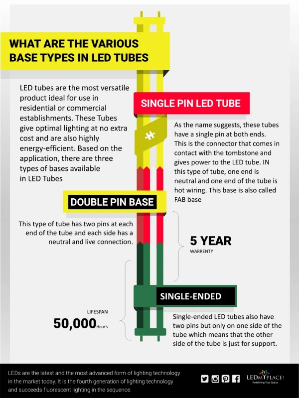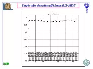
Single tube detection efficiency BIS-MDT
140 likes | 299 Vues
Single tube detection efficiency BIS-MDT. GARFIELD Simulation. Anode wire voltage as a function of the distance from the wire. Electric field as a function of the drift path. Muon track in a distance of 0.1 cm from the anode wire. GARFIELD Simulation. Longitudinal diffusion coefficient.

Single tube detection efficiency BIS-MDT
E N D
Presentation Transcript
GARFIELD Simulation Anode wire voltage as a function of the distance from the wire Electricfield as a function of the drift path Muon track in a distance of 0.1 cm from the anode wire
GARFIELD Simulation Longitudinal diffusion coefficient Transverse diffusion coefficient Electron drift velocity(incm/μsec)as a function of the drift path Ion mobility as a function of the electric field Diffusion coefficients (transverse and longitudinal) as a function of the electric field
Operation Principle A muonwith pT=1ΤeV/c has a track sag τροχιά of500 μm in a magnetic field 0.4 Τ (mean value). Momentum resolution of 10requires precision of 50 μmin the muon track sag. μ
Electronic Signal • PM Analog Signal • Amplitude 400mV • Time Width20ns • PM Logic Signal • Preamplifier • Discriminator (constant fraction) • Amplitude600mV • Time Width14ns
Hodoscope Logic Diagram Meantimer : Time resolution 1 ns TDC: Time resolution 50 ps on 100 ns range System time resolution 1,5-2,0 ns Spatial resolution 20 cm
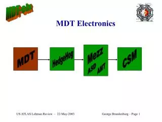
Chamber BIS-MDT Gas Manifold Parallel gas supply at each tube at each multilayer Hedgehog cards Decouple the signals from the wires and provide discharge protection for the amplifier inputs Mezzanine cards 4 Amplifier Shaper Discriminator chips 1 TDCchip
Hodoscope time resolution Time resolution of a system of a scintillator + small(15151 cm3) reference scintillator Small contribution to the overall time resolution
BIS-MDT ‘BEATRICE’ atthe X5/GIF area Cosmic muons Cosmic muons in presence of the background of the source Cs137Photons 662 keV, 740 GBq (3/1997), t1/2=30 y Photon flux at 4 m = 0,86105 cm-2s-1
Chamber BIS-MDT electronics Pseudo-differential pairof preamplifiers (Active and Dummy) Differential amplifier (gain) – Two stages of Differential Amplifiers (gain & bipolar shaping) ShaperDiscriminator ADC (leading edge slew correction timing resolution)
MDT Operation Principle Inefficiency due to a δ-electronshadowing the muon. Probability Distance Discreteness of the ionization mechanismLower resolution close to the wire Decrement of the track-wire distance Large fluctuations
MDT time spectrum to to tmax tmax t1 t1 Velocity Dependence Constant TDC Spectrum