Analysis vs. Design Stage
Analysis vs. Design Stage. During requirement analysis stage What is the problem? What can be improved? What does the user wants? What are the services & constraints of the system? During design stage How will the system be designed to meet user requirements?

Analysis vs. Design Stage
E N D
Presentation Transcript
Analysis vs. Design Stage • During requirement analysis stage • What is the problem? • What can be improved? • What does the user wants? • What are the services & constraints of the system? • During design stage • How will the system be designed to meet user requirements? • How will the user interface look like? • How will the database (files) be designed?
Design Parts • Software packaging design • Architecture design • Component design • Data structure design • Algorithm design • User interface design • Database and file design
Software architecture • The design process for identifying the sub-systems making up a system and the framework for sub-system control and communication is architectural design • The output of this design process is a description of thesoftware architecture.
Architectural design • An early stage of the system design process. • Represents the link between specification and design processes. • Often carried out in parallel with some specification activities. • It involves identifying major system components and their communications.
Advantages of explicit architecture • Stakeholder communication • Architecture may be used as a focus of discussion by system stakeholders. • System Quality • The architecture has a major effect on whether the system meets its non-functional requirements. • System implementation • The architecture affects the implementation effort of the system code • Large-scale reuse • The architecture may be reusable across a range of systems.
Architecture and system characteristics • Performance • Localise critical operations and minimise communications. Use large rather than fine-grain components. • Security • Use a layered architecture with critical assets in the inner layers. • Safety • Localise safety-critical features in a small number of sub-systems. • Availability (Reliability) • Include redundant components and mechanisms for fault tolerance. • Maintainability • Use fine-grain, replaceable components.
Architectural conflicts • Using large-grain components improves performance but reduces maintainability. • Introducing redundant data improves availability but makes security more difficult. • Localising safety-related features usually means more communication so degraded performance.
System structuring • Concerned with decomposing the system into interacting sub-systems. • The architectural design is normally expressed as a block diagram presenting an overview of the system structure. • More specific models showing how sub-systems share data, are distributed and interface with each other may also be developed.
Box and line diagrams • Very abstract - they do not show the nature of component relationships nor the externally visible properties of the sub-systems. • However, useful for communication with stakeholders and for project planning.
Architectural design decisions • Architectural design is a creative process so the process differs depending on the type of system being developed. • However, a number of common decisions span all design processes.
Architectural design decisions • Is there a generic application architecture that can be used? • How will the system be distributed? • What architectural styles are appropriate? • How will the system be decomposed into modules? • What control strategy should be used? • How will the architectural design be evaluated? • How should the architecture be documented?
Architecture reuse • Systems in the same domain often have similar architectures that reflect domain concepts. • Application product lines are built around a core architecture with variants that satisfy particular customer requirements.
Architectural models • Used to document an architectural design. • Static structural model that shows the major system components. • Dynamic process model that shows the process structure of the system. • Interface model that defines sub-system interfaces. • Relationships model such as a data-flow model that shows sub-system relationships. • Distribution model that shows how sub-systems are distributed across computers.
Coupling and Coherence Goal: Reduce system complexity while allowing change Coherence measures dependency among modules High coherence: The classes (modules) in the subsystem perform similar tasks and are related to each other via associations Low coherence: Lots of miscellaneous classes (modules), no relationships Coupling measures dependency among subsystems High coupling: Changes to one subsystem will have high impact on the other subsystem Low coupling: A change in one subsystem does not affect any other subsystem Good Design
Architectural styles • The architectural model of a system may conform to a generic architectural model or style. • An awareness of these styles can simplify the problem of defining system architectures. • However, most large systems are heterogeneous and do not follow a single architectural style.
Examples of Architectural Styles Client/Server Peer-To-Peer Data Repository Abstract machine or layered style.
The repository model • Sub-systems must exchange data. This may be done in two ways: • Shared data is held in a central database or repository and may be accessed by all sub-systems; • Each sub-system maintains its own database and passes data explicitly to other sub-systems. • When large amounts of data are to be shared, the repository model of sharing is most commonly used.
Repository model characteristics • Advantages • Efficient way to share large amounts of data; • Sub-systems need not be concerned with how data is produced Centralised management e.g. backup, security, etc. • Disadvantages • Sub-systems must agree on a repository data model. Inevitably a compromise; • Data evolution is difficult and expensive; • No scope for specific management policies; • Difficult to distribute efficiently.
Client-server model • Distributed system model which shows how data and processing is distributed across a range of components. • Set of stand-alone servers which provide specific services such as printing, data management, etc. • Set of clients which call on these services. • Network which allows clients to access servers.
Client-server characteristics • Advantages • Distribution of data is straightforward; • Makes effective use of networked systems. May require cheaper hardware; • Easy to add new servers or upgrade existing servers. • Disadvantages • No shared data model so sub-systems use different data organisation. Data interchange may be inefficient • Redundant management in each server; • No central register of names and services - it may be hard to find out what servers and services are available
Abstract machine (layered) model • Used to model the interfacing of sub-systems. • Organises the system into a set of layers (or abstract machines) each of which provide a set of services. • Supports the incremental development of sub-systems in different layers. When a layer interface changes, only the adjacent layer is affected. • However, often artificial to structure systems in this way.
Modular decomposition styles • Styles of decomposing sub-systems into modules. • No rigid distinction between system organisation and modular decomposition.
Sub-systems and modules • A sub-system is a system in its own right whose operation is independent of the services provided by other sub-systems. • A module is a system component that provides services to other components but would not normally be considered as a separate system.
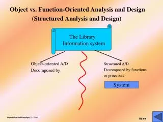
Modular decomposition • Another structural level where sub-systems are decomposed into modules. • Two modular decomposition models covered • An object model where the system is decomposed into interacting object (Object oriented design) • A pipeline or data-flow model where the system is decomposed into functional modules which transform inputs to outputs (Physical data flow diagram).
Control styles • Are concerned with the control flow between sub-systems. Distinct from the system decomposition model. • Centralised control • One sub-system has overall responsibility for control and starts and stops other sub-systems. • Event-based control • Each sub-system can respond to externally generated events from other sub-systems or the system’s environment.
Centralised control • A control sub-system takes responsibility for managing the execution of other sub-systems. • Call-return model • Top-down subroutine model where control starts at the top of a subroutine hierarchy and moves downwards. Applicable to sequential systems. • Manager model • Applicable to concurrent systems. One system component controls the stopping, starting and coordination of other system processes. Can be implemented in sequential systems as a case statement.
Event-driven systems • Driven by externally generated events where the timing of the event is outwith the control of the sub-systems which process the event. • Two principal event-driven models • Broadcast models. An event is broadcast to all sub-systems. Any sub-system which can handle the event may do so; • Interrupt-driven models. Used in real-time systems where interrupts are detected by an interrupt handler and passed to some other component for processing.
Broadcast model • Effective in integrating sub-systems on different computers in a network. • Sub-systems register an interest in specific events. When these occur, control is transferred to the sub-system which can handle the event. • Control policy is not embedded in the event and message handler. Sub-systems decide on events of interest to them. • However, sub-systems don’t know if or when an event will be handled.
Interrupt-driven systems • Used in real-time systems where fast response to an event is essential. • There are known interrupt types with a handler defined for each type. • Each type is associated with a memory location and a hardware switch causes transfer to its handler. • Allows fast response but complex to program and difficult to validate.