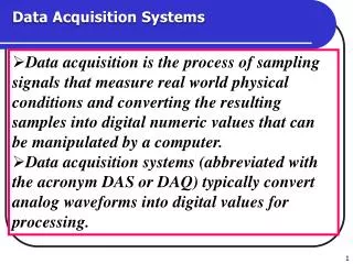
Data Acquisition and Control Systems
HYTEC ELECTRONICS LIMITED. Data Acquisition and Control Systems. Motor Control and Power Drive Support. Graham Cross. graham@hytec-electronics.co.uk. The system consists of 3 main parts: The controller – In this example, housed in an Industry Pack on a VME64x carrier card.

Data Acquisition and Control Systems
E N D
Presentation Transcript
HYTEC ELECTRONICS LIMITED Data Acquisition and Control Systems Motor Control and Power Drive Support Graham Cross graham@hytec-electronics.co.uk
The system consists of 3 main parts: • The controller – In this example, housed in an Industry Pack on a VME64x carrier card. • An interfacing block - DIN rail mounting. • A power driving system - 19” rack mounting.
1. The Controller Hytec 8601 - 4 channel (axis) stepper motor controller in Industry Pack format
VME64x 4 Site Industry Pack Carriers • All versions have full control logic and interrupt handling. • 8002 Standard card 8Mhz IP speed. • 8003 As 8002 but with SHARC DSP and link ports. • 8004 As 8002 but with 8 / 32Mhz IP speed and MBLT readout of all 4 sites in one 64 bit cycle
Industry Pack Stepper Motor Controller 8601 - 4 axes • A 32-bit step register, which sets the number of steps in the next movement, writeable and readable at any time, which counts down to '0'. • A 32-bit absolute position up/down counter, which records movements (writeable and readable). This counter counts all movements including JOG. This counter may follow step pulses sent out from the board or count encoder pulses from an external incremental encoder with quadrature outputs. • A 16-bit Start/Stop Speed Register, which sets the speed at which a movement will start, programmed in steps per second. • A 16-bit Travel Speed Register, which sets the speed at which the motor will run after accelerating, programmed in steps per second. • A 16-bit Ramp Rate Register, which sets the rate at which speed will increase or decrease during ramping, programmed in steps per second per second. Minimum value 64 s/s/s. • A 16-bit Control and Status Register through which the status of the drive, the controller and the limit switches can be observed (run/stop, hit limit, driver dead etc.). • A 16-bit Interrupt Mask Register which controls which CSR bits may generate interrupts. • Additional GO bit to start all 4 axes at once. • The counters can be read on the fly via a shadow register. • Each channel (axis) has four logic outputs and 8 logic inputs to cater for a wide variety of applications. • Able to read the module identity, manufacturer, model, revision and module serial number from an onboard ID ROM. 5
8601 Motor axis CSR functions: • BIT • 0 RESET – Write ‘1’ clears all bits of all registers for this axis. • Negative Limit – ‘1’ means limit switch is open (Read 0nly) • Positive Limit – ‘1’ means limit switch is open (Read 0nly) • Home Limit – ‘1’ means limit switch is open (Read 0nly) • Drive Limit - ‘1’ means limit switch is open (Read 0nly) • GO – write ‘1’ to start a movement of the number of steps programmed. Write ‘0’ to soft stop. • JOG – ‘write ‘1’ to start free running movement. Write ‘0’ to slow down and stop. • ED - Encode detected. A ‘1’ in this bit indicates that a valid clock encode pulse detected. • UE – Use Encoder. ‘1’ means the absolute position should count encoder pulses. • OP1 – controls spare output 1 on the interface. • OP2 – controls spare output 2 on the interface. • Direction – ‘1’ is positive, towards the positive limit. • ABORT – write ‘1’ to stop immediately. • DONE – set as ‘1’ on completion of a movement. • Interrupt Enable – ‘1’ is enable. • Stop at Home – ‘1’ means stop if the home limit is encountered.
HYTEC VDB8906 DIN Rail Mounted Stepper Motor & Encoder Terminal Board
HYTEC VDB8906 DIN Rail Mounted Stepper Motor & Encoder Terminal Board The Interface performs basic signal conditioning and buffering of all inputs and outputs. Includes RS422 level conversion for encoder signals if needed. The interface to the controller is a standard 50 way SCSI-II cable to our 8304 straight through transition card. The connections to the driver are through 15 way D connectors. The unit is modeled on the OMS interface unit for the VME58 motor controller card. Also supports our 8513 Quadrature Encoder reader Industry Pack. An opto-isolated version available soon.
HYTEC SMDS – 4 Power Driver • Houses 4 drive cards and a common logic card. • Supports either: • Old style Unipolar (L/R) driver with external current limit resistors. • Bipolar driver with current limit by PWM (push/pull). • Supports 4 phase hybrid steppers, full or half step. • Also support for 3 or 5 phase motors. • Up to 5 amps current per phase • Internal or external PSU
Some figures for the SMDS-4 system: • Step rate: 1- 65,535 steps per second • Ramp rate: 64 - 50,000 steps per second, linear • Constant start / stop speed is available by setting ramp rate to zero. • Manual controller available for independent testing: • select motor • select direction • select speed on knob 500 – 5000 steps /sec • GO button
Features of the HYTEC solution • Direct motion control with a common start. • Ability to mix L/R and chopped drive cards • Wide variety of control and monitoring signals for a comprehensive system application.
Example application – as used at LCLS • Wanted control for wire scanners and collimators. • Replacing an old CAMAC system. • Needed L/R drive because they had 300 foot cables. • Lower EMC / noise with L/R on long cables. • Wanted 5 amp L/R drive and 24 volt supply. • Bipolar chopped drive had been giving trouble. • Needed large PSU, 5 amps/phase, 10 amps/ motor • 4 motors meant 40 amps at 24 volts • Used external rack mount PSU. • Can use 3 PSU modules in current sharing configuration to drive up to 1, 2 or 3 of our chassis.
Example application – as used at LCLS • Contacts for this motor application at LCLS: • Doug Murray, Bob Fuller and James Bong • Support for Hytec 8601 with EPICS motor record being developed by Peter Dennison (DLS) and Mark Rivers (APS).
9010 IOC BladeRack mounting EPICS IOC with PC104+ You can drive 24 axes from this box