Data Acquisition Systems
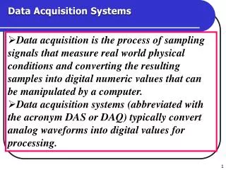
Data Acquisition Systems. Data acquisition is the process of sampling signals that measure real world physical conditions and converting the resulting samples into digital numeric values that can be manipulated by a computer.

Data Acquisition Systems
E N D
Presentation Transcript
Data Acquisition Systems • Data acquisition is the process of sampling signals that measure real world physical conditions and converting the resulting samples into digital numeric values that can be manipulated by a computer. • Data acquisition systems (abbreviated with the acronym DAS or DAQ) typically convert analog waveforms into digital values for processing.
A data acquisition system consists of many components that are integrated to: Sense physical variables (use of transducers) Condition the electrical signal to make it readable by an A/D board. Convert the signal into a digital format acceptable by a computer Process, analyze, store, and display the acquired data with the help of software Contd. Data Acquisition System
Data Acquisition System Signal Conditioner Analog Signal ADC Digital Processing Communication
Sensors that convert physical parameters to electrical signals Sense physical phenomena and translate it into electric signal. • The components of data acquisition systems include: Sensor(Transducers) • Displacement • Level • Electric signals • ON/OFF switch • Temperature • Pressure • Light • Force
Signal conditioning circuitry to convert sensor signals into a form that can be converted to digital values. Functions: modify the analog signal to match the performance of the ADC Pre-filtering: remove undesirable high frequency components Amplification: amplify the signal to match the dynamic range of the ADC Signal Conditioning
Analog-to-Digital Conversion • Most signals are naturally analog (e.g. a voltage) • Digital techniques are often more useful: data storage, processing, computing, error free signal transmission etc. • We need ways to convert analog signals to digital • Want A/D converters to be fast, accurate and cheap • Before a computer can process analog information, we must first use an analog-to-digital converter (ADC) to transform the analog values into digital binary values.
It can be the most critical factor in obtaining reliable, high performance operation. Transforms the PC and DAQ hardware into a complete DAQ, analysis, and display system. Different alternatives: Programmable software. Data acquisition software packages. Data Acquisition Software
Successive-approximation A/D converter • The successive approximation ADC has been the mainstay of data acquisition systems for many years. • A successive approximation ADC is a type of analog-to-digital converter that converts a continuous analog waveform into a discrete digital representation via a binary search through all possible quantization levels before finally converging upon a digital output for each conversion.
Contd. Successive-approximation A/D converter • The successive-approximation A/D converter consists of: • D/A converter • Comparator • Success-approximation register . • Conversion process starts at Maximum range (MSB) and steps down through a defined sequence to the (LSB) until correct reading is found using a DAC and an analog comparator circuit.
Contd. Successive-approximation A/D converter • Successive Approximation ADC Block Diagram. • Key • DAC = Digital-to-Analog converter • EOC = end of conversion • SAR = successive approximation register • S/H = sample and hold circuit • Vin = input voltage • Vref = reference voltage
Contd. Successive-approximation A/D converter • The successive approximation Analog to digital converter circuit typically consists of four chief sub circuits: • A sample and hold circuit to acquire the input voltage (Vin). • An analog voltage comparator that compares Vin to the output of the internal DAC and outputs the result of the comparison to the successive approximation register (SAR).
Contd. Successive-approximation A/D converter • A successive approximation register sub circuit designed to supply an approximate digital code of Vin to the internal DAC. • An internal reference DAC that, for comparison with VREF, supplies the comparator with an analog voltage equal to the digital code output of the SARin.
Operation of the successive-approximation A/D converter • The successive approximation register is initialized so that the most significant bit (MSB) is equal to a digital 1. • This code is fed into the DAC, which then supplies the analog equivalent of this digital code (Vref/2) into the comparator circuit for comparison with the sampled input voltage. • If this analog voltage exceeds Vin the comparator causes the SAR to reset this bit; otherwise, the bit is left a 1.
Operation of the successive-approximation A/D converter • Then the next bit is set to 1 and the same test is done, continuing this binary search until every bit in the SAR has been tested. • The resulting code is the digital approximation of the sampled input voltage and is finally output by the SAR at the end of the conversion (EOC).
Example:Operation of the successive-approximation A/D converter
Successive Approximation ADC Example • Goal: Find digital value Vin • 8-bit ADC • Vin = 7.65 • Vfull scale = 10
Successive Approximation ADC Example • Vfull scale = 10, Vin = 7.65 • MSB LSB • Compare to Vin • Vin > Average MSB = 1 • Vin < Average MSB = 0 • Bit 7 • (Vfull scale +0)/2 = 5 • 7.65 > 5 Bit 7 = 1
Successive Approximation ADC Example • Vfull scale = 10, Vin = 7.65 • MSB LSB • Average high/low limits • Compare to Vin • Vin > Average MSB = 1 • Vin < Average MSB = 0 • Bit 6 • (Vfull scale +5)/2 = 7.5 • 7.65 > 7.5 Bit 6 = 1
Successive Approximation ADC Example • Vfull scale = 10, Vin = 7.65 • MSB LSB • Average high/low limits • Compare to Vin • Vin > Average MSB = 1 • Vin < Average MSB = 0 • Bit 5 • (Vfull scale +7.5)/2 = 8.75 • 7.65 < 8.75 Bit 5 = 0
Successive Approximation ADC Example • Vin = 7.65 • MSB LSB • Average high/low limits • Compare to Vin • Vin > Average MSB = 1 • Vin < Average MSB = 0 • Bit 4 • (8.75+7.5)/2 8.125 • 7.65 < 8.125 Bit 4 = 0
Successive Approximation ADC Example • Vin = 7.65 • MSB LSB • Average high/low limits • Compare to Vin • Vin > Average MSB = 1 • Vin < Average MSB = 0 • Bit 3 • (8.125+7.5)/2 = 7.8125 • 7.65 < 7.8125 Bit 3 = 0
Successive Approximation ADC Example • Vin = 7.65 • MSB LSB • Average high/low limits • Compare to Vin • Vin > Average MSB = 1 • Vin < Average MSB = 0 • Bit 2 • (7.8125+7.5)/2 = 7.65625 • 7.65 < 7.65625 Bit 2 = 0
Successive Approximation ADC Example • Vin = 7.65 • MSB LSB • Average high/low limits • Compare to Vin • Vin > Average MSB = 1 • Vin < Average MSB = 0 • Bit 1 • (7.65625+7.5)/2 = 7.578125 • 7.65 > 7.578125 Bit 1 = 1
Successive Approximation ADC Example • Vin = 7.65 • MSB LSB • Average high/low limits • Compare to Vin • Vin > Average MSB = 1 • Vin < Average MSB = 0 • Bit 0 • (7.65625+7.578125)/2 = 7.6171875 • 7.65 > 7.6171875 Bit 0 = 1
Successive Approximation ADC Example • 110000112 = 19510 • 8-bits, 28 = 256 • Digital Output • 195/256 = 0.76171875 • Analog Input • 7.65/10 = 0.765
Given an analog input signal whose voltage should range from 0 to 15 volts, and an 8-bit digital encoding, calculate the approximate encoding for 5 volts. Trace the successive-approximation approach to find the correct encoding. Exercise