C-Rack Geometry and ORCA
C-Rack Geometry and ORCA. Ivan D Reid Brunel University. ORCA Reconstruction with C-Rack. Attempting to reconstruct OSCAR_2_4_0 ParticleGun tracks in the Cosmic Rack detectors with ORCA led to some problems.


C-Rack Geometry and ORCA
E N D
Presentation Transcript
C-Rack Geometry and ORCA Ivan D Reid Brunel University
ORCA Reconstructionwith C-Rack • Attempting to reconstruct OSCAR_2_4_0 ParticleGun tracks in the Cosmic Rack detectors with ORCA led to some problems. • Mainly due to C-Rack geometry not following assumptions made in the software, based on CMS configuration. • Manually shifted detectors to make them symmetric about the X-axis, and added 1000 mm to Y-positions so that detectors fitted assumptions about layer positions. In particular this solved a “gluing” problem of matching mono and stereo detectors which had not been collected into the same layer. • Problem: Test-Beam seed generator and possibly layer navigator assume particle propagation is primarily in the Z-direction!
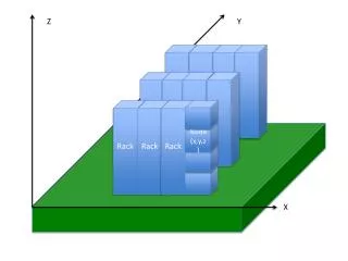
Rotated C-Rack Geometry • To bring C-Rack in line with other “Test-Beam” configurations, the unit was rotated so that the Z-axis was normal to the detector surfaces. • This involved a simple rotation of the whole “Tracker” in tb.xml. • Extra width was also added to the enclosing boxes, as OSCAR will complain about detectors outside these volumes. • Again discovered problems due to assumptions made about detector layout. • Changed to ORCA_8_1_2 for reconstruction and OSCAR_3_2_0 for the ParticleGun. Note that some changes need to be made to the .orcarc file due to parameter renaming!
Some Weird Mathematics! • The next problem was encountered both in IGUANA visualisation (which uses ORCA) and ORCA reconstruction: Error from DetRing::set_size: Det sorting in phi in a ring failed! 1.62759 is smaller than -1.61698 • Tracking this error led to the following code: void DetRing::set_size() { // sort dets inside the ring sort( theDets.begin(), theDets.end(), DetLessPhi()); // Check if the sort worked - don't ask why for ( det_p_iter itmp=theDets.begin(); itmp!=theDets.end()-1; itmp++) { if ( (**(itmp+1)).position().phi() - (**itmp).position().phi() < 0) { cout << endl << "Error from DetRing::set_size: " << endl << "Det sorting in phi in a ring failed!" << endl; cout << (**(itmp+1)).position().phi() << " is smaller than " << (**itmp).position().phi() << endl; • Printing the value in the if()clause showed that 1.62759-(-1.61698) = -3.0386! Obviously the phi()method returns an angle class and the mathematical operators are overloaded to return values in the range –p to +p! Changing the test to if ( (**(itmp+1)).position().phi() < (**itmp).position().phi()) solved this problem – the relational operators work as expected.
Making Rings • At this point, the problem of “gluing” mono and stereo detectors surfaced again, with a “ring” of 6 stereo detectors and no monos being passed for gluing. (Note that the code does the ring-finding and gluing twice, once in Z and once in f – I’ve no idea why!) • This was traced to hard-wired constants in a “clustering” routine that were inappropriate for our geometry. • For the time being I have hacked BarrelRingFinder::findZCusters with constants that are more appropriate for us. These should probably be made configurable. • However, the reconstruction then died with a very non-specific error: DATE=20040507161223 HOST=lxplus022.cern.ch PID=2990 NL.EVNT=CARF-ERROR - Severe from SimEventProcessor:consume Error in processing event: [DB=A4835627-30A0-D811-9848-00D0B7B86A8B][CNT=Events_194124cca03011d8984800d0b7b 86a8b][CLID=2F5462EA-A4CE-1ACE-14E2-2FDB19170F89][TECH=00000201][OID=0000001A-00000001] • This error took a couple of days to find, as I had to trace the execution path with diagnostic print statements...
Who’s Caught My Throw? • The abort was finally traced to the routine TkSequentialMduleNumberingScheme::addRingDetUnits which operates on “rings” of detectors. • Simply put, it looks for a detector close in f to zero, otherwise it takes the detector with the smallest positive f to reorder the detectors around. In our case this clustering results in some “rings” with only one detector – which has f < 0! • In this case the code drops through to throw an exception: bool found( false); for ( firstDetUnit = detUnits.begin(); firstDetUnit != detUnits.end(); firstDetUnit++) { if ( (**firstDetUnit).position().phi() > 0) { found = true; break; } } if (!found) throw DetLogicError("TkSequentialMduleNumberingScheme: no positive phi in ring!"); • Unfortunately, there is no code set up to catch this exception, so the stack unwinds until SimEventProcessor catches it. • Produced a running programme by changing the test to if (!found) firstDetUnit = detUnits.begin();
However... • The reconstruction programme now runs to completion with both C-Rack geometries. • However, no seeds are generated, and no tracks are found. • This was expected in the “original” geometry, since the seed-finding assumes layers extend in Z, not Y. • Also “not unexpected” in the rotated geometry since the seed generation only uses the first two layers, and there is very little overlap between these in C-Rack. • Set ParticleGun to fire directly through the overlap region (at X=0), but still no seeds generated. • Examining print-outs of strip hits suggests that a detector re-ordering problem that interfered with my Monte-Carlo “Test-Beam” reconstruction may have arisen again: mapping out the hit detectors in real space gives results that do not correspond to the track configuration, for either geometry. • See the next two slides for the mapping of several single-track events into the detector geometry, with those detectors having at least one hit strip over 50 ADC units being indicated.
Translated C-Rack Geometry – Reported Hits >50 adc Event 1 Event 2 Event 3 Event 4 Event 5 Particles Particles Y Z
Rotated C-Rack Geometry – Reported Hits >50 adc Event 1 Event 2 Event 3 Event 4 Event 5 Y Z Particles
Misled by Printouts • In fact, there is probably no renumbering problem • Different printouts took either the detector index or the detector sort order! • There seems also to be some difference in sort order in different places where DetUnits have the same Z (i.e. non-unique sort).
Ahh, That’s Better! This plot shows the rotated geometry with the index numbers in black and the ordering in red. Coloured dots show positions for hits >50 adc. (Positions are detector centres, not exact hits!) Perhaps still some anomalies – see magenta hit for DetUnit 243! Also some doubts about stereo detectors… Beam Z Y
Conclusion • Investigation in the seed generator showed that the layers were not ordered in Z. • Searching through the hits to find the layers that have the two smallest Z values led to seeds which gave reconstructed tracks for five of ten simulated events. • Work continues to discover what criteria are required for layer sorting for successful track following.