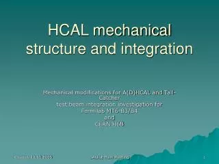
Mechanical and Integration
Mechanical and Integration. CD0 Walkthru, 19-Dec, 2007 Eric Anderssen, LBNL. Mechanics Integration and Design. HFT Pixel Structures, Cooling, and Insertion Mechanics (Service Supports) Integration and Support of IST Structures and Services

Mechanical and Integration
E N D
Presentation Transcript
Mechanical and Integration CD0 Walkthru, 19-Dec, 2007 Eric Anderssen, LBNL
Mechanics Integration and Design • HFT Pixel Structures, Cooling, and Insertion Mechanics (Service Supports) • Integration and Support of IST Structures and Services • Global Supports Design, Integration with FGT and SSD (Support Cones) • Interface Definition and Control • Configuration Control and Documentation • Eventually: Production Planning, Cost, and Schedule
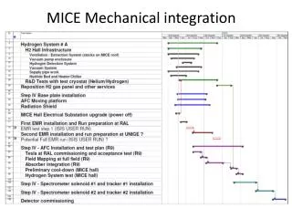
Production Planning • This is obviously too early to present any form of production plan • Cost and Schedule estimations do rely on at least some assumptions • A crude schedule of what is needed when exists • LBNL has the capability to fabricate all of the proposed mechanical structures if required • This is not to say we know who will build what or where they will be built • Goal is to have a model of the distributed production and assembly planning by CD1
Configuration Control • Nothing in place at present, but needs are small until layout is optimized fully • Have sought to generate ‘layout drawings’ showing sections of STAR’s IFC and associated detectors (J. Scheblien sp?) • Goal is to have controlled envelope drawings of sections of HFT in each configuration (changes by run year) • Intent on leveraging ‘e-room’ and ‘Windchill’ PDM software tools in support of this effort • Each allows for versioning, revision control and approval processes for normal and CAD documents with external access by collaborators • Establish controlled Requirements Documents • Have in place at least skeletons by CD1
Interfaces • HFT has both Internal and External Interfaces • Internal Interfaces are easier to control, and are well managed by the concurrent design team • Will add rigor to this with controlled drawings later—after geometry settles • External Interfaces are not wholly in hand • HFT will support the Beam Pipe—no solid design for this exists • FGT needs to modify current support cone, as does HFT—close coordination is required • SSD requires that concurrent modification of end cones by both HFT and FGT consider its support • Other Detectors, e.g. FTPC or others as yet unnamed may impinge upon design envelopes • Need to establish Configuration Control of Envelopes, thus Interfaces First
Global Integrating Structures • FGT requires a new West Cone in ’09, but SSD wants to be in during the ’08 run if possible • New West Cone (NWC) needs to be available by ’09, but East Cone can still be used • NWC + old East Structure must be able to support SSD • HFT requires a new East Cone, or at least a modified East Cone • Following is a proposal which meets these conditions
Cut Apart Current Cones August 2009 Keep at Brookhaven Send to Berkeley Old East Cone and most of Beams to be reused to support New West Cone Old West cone refurbished into New East Cone in Berkeley Cut Carbon Elliptical Beams avoiding Al Insert 7
Modified East Cone and Install with New West Cylinder ~1.5m Some Tooling Required… Buck Plate aimed for Easy Swap of replacement • View as Temporary Fix—Should be ACAP (as cheap as possible) • Supports end of New West Cone/FGT • Replicates Old Beam Pipe Interfaces • Includes SSD if required • Only for summer ’09 to ‘10 • Wholly Machined/Bonded Solution • Tooling to locate Buck Plate while bonding is required… 8
Goal—Swap-in Replacement and Install pixels – summer 2010 New East Cone with Cylindrical Shell made from Old West Cone Swap in by matching Bolted Interface to New West Cone… Include SSD interface On Shell Modification Will Take Up Length… Should Be Same Length 9
Inner Support Cylinder (ISC) SSD Supported on outside ISC fits inside and is supported by the cone ISC supports IST on outside ISC supports pixel and beam pipe inside ISC 10
HFT Pixel Mechanics • Contracted ARES company for analysis on cooling, precision mount design and refinement of ladder stability. • Phone meetings weekly • First results – • We will need Sub-Ambient Cooling • Simplified Precision Mount • Sector Stability seems adequate • First stage report due in March • Results of Thermo-Structural Stability • Kinematic mount design • Move toward construction of prototypes—later verification against models 11
Pixel support structure End view 8 cm radius 2.5 cm radius Inner layer Outer layer ALICE style carbon support beams (green) 12
Sector/ladder design carbon composite support beam thinned MAPS chips 2 cm by 2 cm, 50 µm thick multilayer aluminum kapton flex circuit cable for signal and power thin carbon composite substrate 13
Pixel placement concept • Detector assembly slides in on rails • Parallelogram hinges support the two detector halves while sliding • Cam and follower controls the opening of the hinges during insertion and extraction • Detector support transfers to kinematic dock when positioned at the operating location pixel support hinges kinematic dock sliding carriage cam followers and linear cam slide rails 15
Cam guided insertion operation Closed Open 16
Two sector patch installation – summer 2010 • Requires that all of delivery system, and kinematic mounts are available by then • New Beam Pipe, ISC, and Modified East Cone • Production Electronics and additional stave assemblies can lag 20