Download

1 / 15
160 likes | 334 Vues
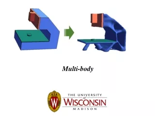
Using Abaqus to Enable Accurate Stress Predictions of a Multi-Body System with Sliding Contact. George Antoun, Clark Briggs ATA Engineering, Inc. 2014 Simulia Customer Conference Providence, RI May 20-22, 2014. ATA Engineering, Inc. The right people. The right skills. The right experience.

E N D
Using Abaqus to Enable Accurate Stress Predictions of a Multi-Body System with Sliding Contact George Antoun, Clark Briggs ATA Engineering, Inc. 2014 Simulia Customer Conference Providence, RI May 20-22, 2014
ATA Engineering, Inc.The right people. The right skills. The right experience.
The standard loads/margins two-step for complex mechanisms Actuator Loads Loads Development Stress Evaluation Enveloping Dedicated MBD codes Detailed FEM Margins Design Updates Challenges Enveloping loads often causes conservatism/design inefficiency Maintaining version control can be difficult: Loads/stress often separate groups Loads/stress models use different modeling platforms
Objective to explore/demonstrate all-FEM approach • Use Abaqus to simulate kinematic operation of flexible MBD model that … • uses a single model/simulation for loads and stress • includes sliding contact with flexible component, enabling accurate local stress predictions • accounts for coupling of flexible components with actuated motions • Examine modeling strategies to facilitate fast model updates in highly dynamic design environment
Dedicated MBD codes have their uses …. and limitations Dedicated MBD codes … But … Enable rapid model development, fast runtime Fewer DOF means less resolution/ accuracy Neglects coupling of flexible components, may overpredicts loads Use rigid components Accounts for coupling, not always appropriate for stress Can include modal flexibility Can’t recover local stress, detailed FEM still required Can include sliding contact Cannot include component nonlinearities (mtrl or geometric) Rudimentary contact enforcement
Requirements of demonstration model derived through customer discussions • Model Overview*: • 31 rigid parts • 25 articulating joints (connectors) • 1 flexible rail (S4, C3D8) • 4 contact domains (bearing block/T-slot) • Requirements: • Articulating joints with enforced motion • Include flexible components • Accurate sliding contact on flexible component • Must enable rapid design updates • Goal: • Size joint actuators • Verify design of rail *Mannequin CAD from user “Tony” on grabcad.com
Examined two ways to model rigid components *MASS, *COUPLING *KINEMATIC, *DISPLAY BODY MESH + *RIGID BODY • Pros • Easy component setup • Mass props from mesh • Easy to change from rigid/ flexible • Can be used for contact/clearance checks • Con • Computationally expensive • Pros • Easy mass props updates • Computationally efficient • Con • Setup is user-intensive
Joint and rail modeling *CONTACT at block-rail interface (x4) Coincident ref points and connector elements represent joints *RIGID BODY bearing blocks (x4) 1 coordinate system per connector *CONNECTOR MOTION defines actuated motion Flexible rail (S4, C3D8)
Simulation recovers local stress, includes flexible component coupling • Flexible rail case best suited to /Standard • Dominant low-frequency, stress-fidelity mesh • Rigid rail case well suited to either solver • Excluded rail since 4 connection points are statically indeterminate No contact definition
Solution type and modeling choices dramatically affect runtime • Rigid component modeling method strongly affects runtime • Including flexible rail also strongly affects runtime • Flex rail model 200k DOF vs. rigid rail model 6k DOF • Despite higher runtime of flex rail case: • Includes coupling effects on actuators More accurate • Provides stress results directly No load enveloping required • Loads/stress from single model Easier version control 110 CPUs, high-end desktop, max time step = 0.02 sec 2 No rail or contact included in simulation 6k DOF 200k DOF
Modeling recommendations for a dynamic design environment, 1/3 • Use intuitive naming for all modeling features • No graphics-based selection for connectors/constraints/loads/boundary conditions, must select from list • All connectors require coincident reference points, coordinate systems • Keep in mind alpha-numeric sorting to group related entities
Modeling recommendations for a dynamic design environment, 2/3 Elem Set: L_Elbow • Avoid graphically selecting immature design features for assignments • Recreating wire will invalidate all graphically selected features • Using named sets (*ELSET) will minimize rework • Valid for wires, surfaces, edges, etc. Wire f(t) *CONNECTOR SECTION *CONNECTOR MOTION
Modeling recommendations for a dynamic design environment, 3/3 Geometric Vertex • Avoid directly selecting geometric vertices for ref point creation • When replacing instances, ref points and all dependent items become invalid • Instead manually specify coordinates of ref points or datum points X, Y, Z Datum Point Reference Point Reference Point Wires/ Connectors *COUPLING, *RIGID BODY, *DISPLAY BODY *ORIENTATION
Summary • Can use all-Abaqus simulation for loads and accurate stress recovery • Can includes local contact stress • Correctly accounts for sliding contact • Runtime sensitive to rigid component modeling strategy • To enable rapid model updates • Use intuitive naming for modeling features • Use named sets • Keep reference points independent of geometric vertices