Function Oriented Design and Detailed Design
Function Oriented Design and Detailed Design. Software Design. Noun : Represents the abstract entity -design- of a system Design of an existing system Every existing system has a design Design of a system to be constructed Design is a plan for a solution Verb :


Function Oriented Design and Detailed Design
E N D
Presentation Transcript
Software Design • Noun : • Represents the abstract entity -design- of a system • Design of an existing system • Every existing system has a design • Design of a system to be constructed • Design is a plan for a solution • Verb : • The process of design(ing), which results in a design • Resulting design is a plan for a solution
Design… • Design activity begins with a set of requirements • Design done before the system is implemented • Design is the intermediate language between requirements and code • Moving from problem domain to solution domain • Proceeding from abstract to more concrete representations • Result is the design to be used for implementing the system
Design… • Design is a creative activity • Goal: to create a plan to satisfy requirements • Perhaps the most critical activity during system development • Design determines the major characteristics of a system • Has great impact on testing and maintenance • Design document forms reference for later phases
Levels in Design Process • Architectural design • Identifies the components needed for the system, their behavior, and relationships • We have already discussed it • High Level Design • Really is the module view of the system • I.e. what modules are in the system and how they are organized
Levels.. • Logic design • Components and modules are designed to satisfy their specs • How to implement components • Algorithms for implementing component are designed • Complete design: the architectural design, the high level design, and Logic design of each component
Design Methodologies • Many possibilities for design, methodologies aim to reduce search space • Provide some discipline for handling complexity • Most methodologies deal with high level design • Provide a set of rules for guiding the designer • Rules do not reduce design to a sequence of mechanical steps • Many methodologies exist • Diff. methodologies may be useful for diff. applications
Design Objectives • Goal is to find the best possible design • Have to explore different designs • Evaluation criteria are often subjective and non quantifiable • Major criteria to evaluate a design • Correctness • Efficiency • Maintainability • Cost
Correctness is the most fundamental • Does design implement requirements? • Is design feasible, given the constraints? • Efficiency • Concerned with the proper use of scarce resources - processor & memory • Other factors same, efficiency should be maximized
Maintainability • Most important quality criteria • Most affected by architectural design • Should facilitate testing • Should facilitate discovery and correction of bugs • Make modifying the system easier • Cost • For same quality, minimize cost • Design costs are quite small • Should try to minimize cost in later phases
Design Principles • Design is a creative process • How to create a design from abstract requirements • There are principles for guiding during design • Two fundamental principles in the design process • Problem partition • Abstraction
Problem Partitioning • Basic principle "divide and conquer" • Divide the problem into manageably small pieces • Each piece can be solved separately • Each piece can be modified separately • Pieces can be related to the application • Pieces cannot be independent; they must communicate • Communication adds complexity • As number of components increases, this cost increases • Stop partitioning when cost is more than benefit
Abstraction • Necessary for partitioning • Used in all engg disciplines (all walks of life) • Abstraction of existing components • Represents components as black boxes • Hides the details, provide external behavior • Useful for understanding existing systems • Necessary for using systems • Useful for determining design of existing systems
Abstraction during design process • Components do not exist a priori • To decide how components interact the designer specifies the external behavior of components • Allows concentrating on one component at a time • Permits a component to be considered without worrying about others • Allows designer to control the complexity • Permits gradual transition from abstract to concrete • Necessary for solving parts separately
Functional Abstraction • Employs parameterized subprograms • Specifies the functional behavior of a module • Module is treated as a input/output function • Most languages provide features to support this (e.g. functions, procedures, …) • A functional module can be specified using pre and post conditions
Data Abstraction • An entity in the real world provides some services to the environment it belongs • Similar is the case of data entities • Certain operations are required from a data object • The internals are not of consequence • Data abstraction supports this view • Data is treated as a set of pre defined operations • Only operations can be performed on the objects • Internals are hidden and protected • Modern languages support data abstraction
Top-Down vs Bottom-up Design Top down design • Starts with the system specifications • Defines a module to implement the specs • Specifies subordinate modules • Then treats each specified module as the problem • Refinement proceeds till bottom level modules reached • At each stage a clear picture of design exists • Most natural for handling complex problems • Have been propagated by many • Many design methodologies based on this • Feasibility is not know till the end
Bottom up Design • In we start by designing bottom modules • Building blocks Layers or abstraction or virtual machines • Necessary if existing modules have to be reused • Pure top-down or bottom-up is not possible • In bottom-up must have some idea of the top • Often a combination is used
Modularity • Modularity is the degree to which a system's components may be separated and recombined. • A concept closely tied to abstraction • Modularity supports independence of models • Modules support abstraction in software • Supports hierarchical structuring of programs • Modularity enhances design clarity, eases implementation • Reduces cost of testing, debugging and maintenance • Cannot simply chop a program into modules to get modularly • Need some criteria for decomposition
Coupling • Independent modules: if one can function completely without the presence of other • Independence between modules is desirable • Modules can be modified separately • Can be implemented and tested separately • Programming cost decreases • In a system all modules cannot be independent • Modules must cooperate with each other • More connections between modules • More dependent they are • More knowledge about one module is required to understand the other module. • Coupling captures the notion of dependence
Coupling between modules is the strength of interconnections between modules • In general, the more we must know about module A in order to understand module B the more closely connected is A to B • "Highly coupled" modules are joined by strong interconnection • "Loosely coupled" modules have weak interconnections
Goal: modules as loosely coupled as possible • Where possible, have independent modules • Coupling is decided during architectural design • Cannot be reduced during implementation • Coupling is inter-module concept • Major factors influencing coupling • Type of connection between modules • Complexity of the interface • Type of information flow between modules
The complexity and obscurity of interfaces increase coupling • Minimize the number of interfaces per module • Minimize the complexity of each interface • Coupling is minimized if • Only defined entry of a module is used by others • Information is passed exclusively through parameters • Coupling increases if • Indirect and obscure interface are used • Internals of a module are directly used • Shared variables employed for communication
Coupling increases with complexity of interfaces (eg. number and complexity of parameters) • Interfaces are needed to support required communication • Often more than needed is used (eg. passing entire record when only a field is needed) • Keep the interface of a module as simple as possible
Coupling depends on type of information flow • Two kinds of information: data or control. • Transfer of control information • Action of module depends on the information • Makes modules more difficult to understand • Transfer of data information • Module can be treated as input-output function
Lowest coupling: interfaces with only data communication • Highest: hybrid interfaces
Cohesion • Cohesion refers to the degree to which the elements of a module belong together. • Coupling characterized the inter-module bond • Reduced by minimizing relationship between elements of different modules • Another method of achieving this is by maximizing relationship between elements of same module • Cohesion considers this relationship • Interested in determining how closely the elements of a module are related to each other • In practice both are used
Cohesion of a module represents how tightly bound are the elements of the module • Gives a handle about whether the different elements of a module belong together • High cohesion is the goal • Cohesion and coupling are interrelated • Greater cohesion of modules, lower coupling between module • Correlation is not perfect.
Levels of Cohesion • There are many levels of cohesion. • Coincidental • Logical – conceptually related procedures are grouped together • Temporal - aspects of a system are grouped together which are used during the same phase of execution of a program, i.e. execute close together in time • Communicational - procedures that access the same data are kept together • Sequential - a series of procedures, where one provides input to the next, are kept together • Layer - facilities for providing or accessing a set of services through an API or hardware interface are kept together. There must also be a strict hierarchy in which higher level layers can access only lower-level layers. In other words, the system is effectively divided into layers • Functional - modules which together perform a function (a computation that returns a result and has no side effects) are kept together, and everything else is kept out • Coincidental is lowest, functional is highest • Scale is not linear • Functional is considered very strong
Determining Cohesion • Describe the purpose of a module in a sentence • Perform the following tests • If the sentence has to be a compound sentence, contains more than one verbs, the module is probably performing more than one function. Probably has sequential or communicational cohesion. • If the sentence contains words relating to time, like "first", "next", "after", "start" etc., the module probably has sequential or temporal cohesion.
If the predicate of the sentence does not contain a single specific object following the verb, the module is probably logically cohesive. Eg "edit all data", while "edit source data" may have functional cohesion. • Words like "initialize", "clean-up" often imply temporal cohesion. • Functionally cohesive module can always be described by a simple statement
Summary • Design is a creative activity • Goal is to find the best possible design • Two levels in the design process • Architectural design and logic design • Correctness of design is most fundamental property • Design principles • Problem partitioning • Abstraction • When using functional abstraction aim for • Low coupling • High cohesion • Design Methodologies - a set of rules/steps to guide the designer
Program Structure and Structure Charts • Every program has a structure • Structure Chart - graphic representation of structure • SC represents modules and interconnections • Each module is represented by a box • If A invokes B, an arrow is drawn from A to B • Arrows are labeled by data items • Different types of modules in a SC • Input, output, transform and coordinate modules • A module may be a composite
SC shows the static structure, not the logic • Different from flow charts • Major decisions and loops can be shown • Structure is decided during design • Implementation does not change structure • Structure effects maintainability • Structured Design Methodology (SDM) aims to control the structure
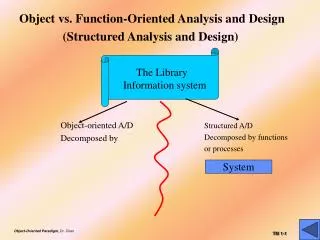
STRUCTURED DESIGN METHODOLOGY • SDM views software as a transformation function that converts given inputs to desired outputs • The focus of SD is the transformation function • Uses functional abstraction • Goal of SDM: Specify functional modules and connections • Low coupling and high cohesion is the objective Transformation functions Output Input
Main Steps in SD • Draw a DFD of the system • Identify most abstract inputs and most abstract outputs • First level factoring • Factoring of input, output, transform modules • Improving the structure
Data Flow Diagrams • SD starts with a DFD to capture flow of data in the proposed system • DFD is an important representation; provides a high level view of the system • Emphasizes the flow of data through the system • Ignores procedural aspects • (Purpose here is different from DFDs used in requirements analysis, thought notation is the same)
Drawing a DFG • Start with identifying the inputs and outputs • Work your way from inputs to outputs, or vice versa • If stuck, reverse direction • Ask: "What transformations will convert the inputs to outputs" • Never try to show control logic. • If thinking about loops, if-then-else, start again • Label each arrow carefully • Make use of * and +, and show sufficient detail • Ignore minor functions in the start • For complex systems, make DGF hierarchical • Never settle for the 1st DGF
Step 2 of SD Methodology • Generally a system performs a basic function • Often cannot be performed on inputs directly • First inputs must be converted into a suitable form • Similarly for outputs - the outputs produced by main transforms need further processing • Many transforms needed for processing inputs and outputs • Goal of step 2 is to separate such transforms from the basic transform centers
Step 2… • Most abstract inputs: data elements in DFG that are furthest from the actual inputs, but can still be considered as incoming • These are logical data items for the transformation • May have little similarity with actual inputs. • Often data items obtained after error checking, formatting, data validation, conversion etc.
Step 2… • Travel from physical inputs towards outputs until data can no longer be considered incoming • Go as far as possible, without loosing the incoming nature • Similarly for most abstract outputs • Represents a value judgment, but choice is often obvious • Bubbles between mai and mao: central transforms • These transforms perform the basic transformation • With mai and mao the central transforms can concentrate on the transformation
Step 2… • Problem View: Each system does some i/o and some processing • In many systems the i/o processing forms the large part of the code • This approach separates the different functions • subsystem primarily performing input • subsystem primarily performing transformations • subsystem primarily performing output presentation
First Level Factoring • First step towards a structure chart • Specify a main module • For each most abstract input data item, specify a subordinate input module • The purpose of these input modules is to deliver to main the mai data items • For each most abstract output data element, specify an output module • For each central transform, specify a subordinate transform module • Inputs and outputs of these transform modules are specified in the DFD
First level factoring is straight forward • Main module is a coordinate module • Some subordinates are responsible for delivering the logical inputs • These are passed to transform modules to get them converted to logical outputs • Output modules then consume them • Divided the problem into three separate problems • Each of the three diff. types of modules can be designed separately • These modules are independent