Function-oriented design
Function-oriented design. Software Engineering Ian Sommerville Chapter 15, 5 th Edition. Objectives. To explain how a software design may be represented as a set of functions which share state To introduce notations for function-oriented design

Function-oriented design
E N D
Presentation Transcript
Function-oriented design Software Engineering Ian Sommerville Chapter 15, 5th Edition
Objectives • To explain how a software design may be represented as a set of functions which share state • To introduce notations for function-oriented design • To illustrate the function-oriented design process by example • To compare sequential, concurrent and object-oriented design strategies
Topics covered • Data-flow design • Structural decomposition • Detailed design • A comparison of design strategies
Function-oriented design • Design with functional units which transform inputs to outputs • Practised informally since programming began • Thousands of systems have been developed using this approach • Supported directly by most programming languages • Most design methods are functional in their approach
Natural functional systems • Some systems are naturally function-oriented • Systems which maintain minimal state information i.e. where the system is concerned with processing independent actions whose outcomes are not affected by previous actions • Information sharing through parameter lists • Transaction processing systems fall into this category. Each transaction is independent
ATM software design loop loop Print_input_message (” Welcome - Please enter your card”) ; exitwhen Card_input ; endloop ; Account_number := Read_card ; Get_account_details (PIN, Account_balance, Cash_available) ; if Validate_card (PIN) then loop Print_operation_select_message ; case Get_button is when Cash_only => Dispense_cash (Cash_available, Amount_dispensed) ; when Print_balance => Print_customer_balance (Account_balance) ; when Statement => Order_statement (Account_number) ; when Check_book => Order_checkbook (Account_number) ; endcase ; Eject_card ; Print (“Please take your card or press CONTINUE”) ; exitwhen Card_removed ; endloop ; Update_account_information (Account_number, Amount_dispensed) ; else Retain_card ; endif ; end loop ;
Functional and object-oriented design • For many types of application, object-oriented design is likely to lead to a more reliable and maintainable system • Some applications maintain little state – function-oriented design is appropriate • Standards and methods for functional design are well-established • Existing systems must be maintained – function-oriented design will be practised well into the future
Functional design process • Data-flow design • Model the data processing in the system using data-flow diagrams • Structural decomposition • Model how functions are decomposed to sub-functions using graphical structure charts • Detailed design • The entities in the design and their interfaces are described in detail. These may be recorded in a data dictionary and the design expressed using a PDL
Topics covered • Data-flow design • Structural decomposition • Detailed design • A comparison of design strategies
Data flow diagrams • Show how an input data item is functionally transformed by a system into an output data item • Are an integral part of many design methods • May be translated into either a sequential or parallel design. In a sequential design, processing elements are functions or procedures; in a parallel design, processing elements are tasks or processes
DFD notation • Rounded rectangle - function or transform • Rectangle - data store • Circles - user interactions with the system • Arrows - show direction of data flow • keywords and/ or. Used to link data flows
Get design name Design name Entity names Design Get entity Sort entity database names names Sorted Produce Link names link report report Data Look up Integrate dictionary entity names reports and Link Design entity descriptions Node descriptions Integrated report report and Sort by Produce type node report Node Print descriptions report Design report generator
Topics covered • Data-flow design • Structural decomposition • Detailed design • A comparison of design strategies
Structural decomposition • Structural decomposition is concerned with developing a model of the design which shows the dynamic structure i.e. function calls • This is not the same as the static composition structure • The aim of the designer should be to derive design units which are highly cohesive and loosely coupled • In essence, a data flow diagram is converted to a structure chart
Decomposition guidelines • For business applications, the top-level structure chart may have three functions namely input, process and output • Data validation functions should be subordinate to an input function • Coordination and control should be the responsibility of functions near the top of the hierarchy
Decomposition guidelines • The aim of the design process is to identify loosely coupled, highly cohesive functions. Each function should therefore do one thing and one thing only • Each node in the structure chart should have between two and seven subordinates
Process steps • Identify system processing transformations • Transformations in the DFD which are concerned with processing rather than input/output activities. Group under a single function in the structure chart • Identify input transformations • Transformations concerned with reading, validating and formatting inputs. Group under the input function • Identify output transformations • Transformations concerned with formatting and writing output. Group under the output function
Produce design report s entity entity names data entity entity names data Get design Collate Gener ate entity names entities repor t Design Design Design name entity repor t names Initial structure chart
Produce design repor ts sor ted entity names sor ted names data entity data Get design Collate Gener ate entity names entities repor t sor ted sor ted entity entity names entity data names data design sor ted entity Integ r ated name names data repor t Get design Get entity Sor t entities Get entity Sor t entities Produce Pr int name names b y name data b y type integ r ated repor t report design entity entity repor t name names data Expanded structure chart
Produce design repor ts sor ted entity names sor ted names data entity data Get design Collate Gener ate entity names entities repor t sor ted sor ted entity names entity entity data names data design sor ted entity Integ r ated name names data repor t Get design Get entity Sor t entities Get entity Sor t entities Produce Pr int name names b y name data b y type integ r ated repor t report Node Link data design design entity entity entity Node data name name names name data repor t Link repor t repor t Design Data Produce Produce database dictionar y link repor t node repor t Final structure chart
Topics covered • Data-flow design • Structural decomposition • Detailed design • A comparison of design strategies
Detailed design • Concerned with producing a short design specification (minispec) of each function. This should describe the processing, inputs and outputs • These descriptions should be managed in a data dictionary • From these descriptions, detailed design descriptions, expressed in a PDL or programming language, can be produced
Get design name Design name Entity names Design Get entity Sor t entity database names names T r a n s f o r m n a m e : S o r t e n t i t y n a m e s ( N a m e l i s t : i n o u t N a m e s ) D e s c r i p t i o n : T h i s t r a n s f o r m t a k e s a l i s t o f e n t i t y n a m e s a n d s o r t s t h e m i n t o a s c e n d i n g a l p h a b e t i c a l o r d e r . Data D u p l i c a t e s a r e r e m o v e d f r o m t h e l i s t . dictionar y I t i s a n t i c i p a t e d t h a t t h e n a m e s w i l l b e r a n d o m l y o r d e r e d a n d t h a t a m a x i m u m o f 2 0 0 n a m e s n e e d b e s o r t e d a t o n e t i m e . A q u i c k s o r t a l g o r i t h m i s r e c o m m e n d e d . Design entity information
Topics covered • Data-flow design • Structural decomposition • Detailed design • A comparison of design strategies
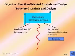
A comparison of design strategies • An example of an office information retrieval system (OIRS) is used to compare different design strategies • Functional design, concurrent systems design and object-oriented design are compared • The OIRS is an office system for document management. Users can file, maintain and retrieve documents using it
F u n c t i o n - o r i e n t e d d e s i g n i s a n a p p r o a c h t o s o f t w a r e d e s i g n w h e r e t h e d e s i g n i s d e c o m p o s e d i n t o a s e t o f i n t e r a c t i n g u n i t s w h e r e e a c h u n i t h a s a c l e a r l y d e f i n e d f u n c t i o n . B y c o m p a r i s o n w i t h o b j e c t - o r i e n t e d d e s i g n , t h e d e s i g n c o m p o n e n t s i n t h i s a p p r o a c h a r e c o h e s i v e a r o u n d a f u n c t i o n w h e r e a s o b j e c t - o r i e n t e d c o h e s i o n i s a r o u n d s o m e a b s t r a c t d a t a e n t i t y . F u n c t i o n - o r i e n t e d d e s i g n h a s p r o b a b l y b e e n p r a c t i s e OIRS user interface Document name Oper ations Kno wn inde x es Current inde x es Chapter 15 Get document Put document Q UIT NEW STYLE Qualifier Search database ‘SE BOOK’ Add inde x 4 documents in w or kspace Documents CLEAR Delete inde x Delete document d i n f o r m a l l y s i n c e p r o g r a m m i n g b e g a n b u t i t w a s o n l y i n t h e l a t e 1 9 6 0 s a n d e a r l y 1 9 7 0 s t h a t i t
Interface description • Operation field. • Pull-down menu allowing an operation to be selected. • Known and current indexes fields • Pull-down menus of indexes • Document name. • Name under which the document is to be filed. • Qualifier field • Pattern used in retrieval. • Current workspace • Contains the documents currently being used. May be edited with word processor
Current w or kspace User command and or Document Document OIRS database database and and Status message Current w or kspace OIRS inputs and outputs
Fetch-execute model procedure Interactive_system is begin loop Command := Get_command; if Command = “quit” then -- Make sure files etc. are closed properly Close_down_system ; exit ; else Input_data := Get_input_data ; Execute_command (Command, Input_data, Output_data) ; end if ; end loop ; endInteractive_system ;
Get Update Document command database database Current Ex ecute Update Current w or kspace Command w or kspace w or kspace Document Put status database message Status message Top-level OIRS DFD
Design decisions • What strategy should be adopted in decomposing Execute command? • Are the input and output data flows processed independently or are they inter-dependent. If independent, there should be a central transform for each processing unit • Is the central transform a series of transforms? If so, each logical element in the series should be a single transformation
User command Identify Selected W or kspace command type DB document update W or kspace update Inde x update command command command Selected document W or kspace Update Update Update w or kspace inde x database Status W or kspace Status Database Kno wn message message update request inde x es Execute command DFD
OIRS design procedure OIRS is begin User := Login_user ; Workspace := Create_user_workspace (User) ; -- Get the users own document database using the user id DB_id := Open_document_database (User) ; -- get the user’s personal index list; Known_indexes := Get_document_indexes (User) ; Current_indexes := NULL ; -- command fetch and execute loop loop Command := Get_command ; exit when Command = Quit ; Execute_command ( DB_id, Workspace, Command, Status) ; if Status = Successful then Write_success_message ; else Write_error_message (Command, Status) ; end if ; end loop ; Close_database (DB_id) ; Logout (User) ; end OIRS ;
Concurrent systems design • Data flow diagrams explicitly exclude control information. They can be implemented directly as concurrent processes. • Logical groups of transformations can also be implemented as concurrent processes e.g. input data collection and checking • The OIRS system can be implemented as a concurrent system with command input, execution and status reporting implemented as separate tasks
User Get Ex ecute input command command Message W or kspace Output editor message OIRS process decomposition
Detailed process design procedure Office_system is task Get_command ; task Process_command is entry Command_menu ; entry Display_indexes ; entry Edit_qualifier ; -- Additional entries here. One for each command end Process_commands ; task Output_message is entry Message_available ; end Output_message ; task Workspace_editor is entry Enter ; entry Leave ; end Workspace_editor ;
Detailed process design task body Get_command is begin -- Fetch/execute loop loop loop Cursor_position := Get_cursor_position ; exit when cursor positioned in workspace or (cursor positioned over menu and button pressed) Display_cursor_position ; end loop ; if In_workspace (Cursor_position) then Workspace_editor.Enter ; elsif In_command_menu (Cursor_position) then Process_command.Command_menu ; elsif In_Known_indexes (Cursor_position) then Process_command.Display_indexes ; elsif In_Current_indexes (Cursor_position) then ... Other commands here ... end loop ; -- Fetch/execute end Get_command ; -- other task implementations here end Office_system ;
Object-oriented design • An object-oriented design focuses on the entities in the system rather than the data processing activities • Simplified OOD here which illustrates a different decomposition
Retrie v al Document Inde x User system Name Name User command File Displa y Get command Retr ie v e Delete entr y Put message Archiv e Add entr y Destro y Initial object identification
New objects required • Workspace • Corresponds to the user’s workspace and provides operations to add and remove documents from the workspace • Index list • Provides facilities to manage a list of indexes • Document database • Corresponds to the database of documents. provides search and retrieval operations
W orkspace Inde x list Document DB Documents Inde x es Documents Status Inde x es Add inde x Add doc. Search Remo v e inde x Remo v e doc. <Other DB Sho w names oper ations> Clear Additional OIRS objects
Object refinement • Retrieval system does not provide services. It coordinates other objects. It has only attributes • Documents and indexes are explicitly named • The individual command components have been bundled into a single attribute User command in Retrieval system • The User object has been replaced by the Display object
Displa y Retrie v al system Command list User command Buttons W or kspace Kno wn inde x es Kno wn inde x es Current inde x es Current inde x es Doc. name Doc. list Qualifier WSpace status Get command Put message Modified OIRS objects
Key points • Function-oriented design relies on identifying functions which transform inputs to outputs • Many business systems are transaction processing systems which are naturally functional • The functional design process involves identifying data transformations, decomposing functions into sub-functions and describing these in detail
Key points • Data-flow diagrams are a means of documenting end-to-end data flow. Structure charts represent the dynamic hierarchy of function calls • Data flow diagrams can be implemented directly as cooperating sequential processes • Functional and object-oriented design result in different system decompositions. However, a heterogeous approach to design is often necessary