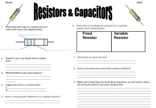
RC (Resistor-Capacitor) Circuits
RC (Resistor-Capacitor) Circuits. AP Physics C. RC Circuit – Initial Conditions. An RC circuit is one where you have a capacitor and resistor in the same circuit. Suppose we have the following circuit:.

RC (Resistor-Capacitor) Circuits
E N D
Presentation Transcript
RC (Resistor-Capacitor) Circuits AP Physics C
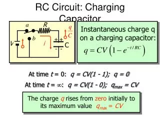
RC Circuit – Initial Conditions An RC circuit is one where you have a capacitor and resistor in the same circuit. Suppose we have the following circuit: Initially, the capacitor is UNCHARGED (q = 0) and the current through the resistor is zero. A switch (in red) then closes the circuit by moving upwards. The question is: What happens to the current and voltage across the resistor and capacitor as the capacitor begins to charge as a function of time? Which path do you think it takes? VC Time(s)
Voltage Across the Resistor - Initially If we assume the battery has NO internal resistance, the voltage across the resistor will be the EMF. e VResistor t (sec) After a very long time, Vcap= e, as a result the potential difference between these two points will be ZERO. Therefore, there will be NO voltage drop across the resistor after the capacitor charges. Note: This is while the capacitor is CHARGING.
Current Across the Resistor - Initially Imax=e/R t (sec) Since the voltage drop across the resistor decreases as the capacitor charges, the current across the resistor will reach ZERO after a very long time. Note: This is while the capacitor is CHARGING.
Voltage Across the Capacitor - Initially e Vcap t (sec) As the capacitor charges it eventually reaches the same voltage as the battery or the EMF in this case after a very long time. This increase DOES NOT happen linearly. Note: This is while the capacitor is CHARGING.
Current Across the Capacitor - Initially Imax=e/R t (sec) Since the capacitor is in SERIES with the resistor the current will decrease as the potential difference between it and the battery approaches zero. It is the potential difference which drives the value for the current. Note: This is while the capacitor is CHARGING.
Time Domain Behavior The graphs we have just seen show us that this process depends on the time. Let’s look then at the UNITS of both the resistance and capacitance. Unit for Resistance = W = Volts/Amps Unit for Capacitance = Farad = Coulombs/Volts
The “Time” Constant It is clear, that for a GIVEN value of "C”, for any value of “R” it effects the time rate at which the capacitor charges or discharges. Thus the PRODUCT of R and C produce what is called the CIRCUIT Capacitive TIME CONSTANT. We use the Greek letter, Tau, for this time constant. The question is: What exactly is the time constant?
The “Time” Constant The time constant is the time that it takes for the capacitor to reach 63% of the EMF value during charging.
Charging Behavior e Is there a function that will allow us to calculate the voltage at any given time “t”? Let’s begin by using KVL Vcap e t (sec) We now have a first order differential equation.
Charging function e • How do we solve this when we have 2 changing variables? • To get rid of the differential we must integrate. To make it easier we must get our two changing variables on different sides of the equation and integrate each side respectively. • Re-arranging algebraically. • Getting the common denominator • Separating the numerator from the denominator, • Cross multiplying. • Since both changing variables are on opposite side we can now integrate.
Charging function e However if we divide our function by a CONSTANT, in this case “C”, we get our voltage function. As it turns out we have derived a function that defines the CHARGE as a function of time.
Let’s test our function e 0.98e 0.95e 0.86e 0.63e Steady State Transient State 0.63e 0.86e 0.95e 1RC 2RC 31RC 4RC 0.98e Applying each time constant produces the charging curve we see. For practical purposes the capacitor is considered fully charged after 4-5 time constants( steady state). Before that time, it is in a transient state.
Charging Functions Likewise, the voltage function can be divided by another constant, in this case, “R”, to derive the current charging function. Now we have 3 functions that allows us to calculate the Charge, Voltage, or Current at any given time “t” while the capacitor is charging.
Capacitor Discharge – Resistor’s Voltage Suppose now the switch moves downwards towards the other terminal. This prevents the original EMF source to be a part of the circuit. e At t =0, the resistor gets maximum voltage but as the capacitor cannot keep its charge, the voltage drop decreases. VResistor t (sec)
Capacitor Discharge – Resistor’s Current Similar to its charging graph, the current through the resistor must decrease as the voltage drop decreases due to the loss of charge on the capacitor. I=e/R IResistor t (sec)
Capacitor Discharge – Capacitor's Voltage The discharging graph for the capacitor is the same as that of the resistor. There WILL be a time delay due to the TIME CONSTANT of the circuit. In this case, the time constant is reached when the voltage of the capacitor is 37% of the EMF.
Capacitor Discharge – Capacitor’s Current Similar to its charging graph, the current through the capacitor must decrease as the voltage drop decreases due to the loss of charge on the capacitor. I=e/R Icap t (sec)
Discharging Functions Once again we start with KVL, however, the reason we start with ZERO is because the SOURCE is now gone from the circuit.
Discharging Functions We now can calculate the charge, current, or voltage for any time “t” during the capacitors discharge.