BASIC ELECTRONICS
BASIC ELECTRONICS. CONTENTS. Resistor Capacitor Diode Transistor. Resistor.


BASIC ELECTRONICS
E N D
Presentation Transcript
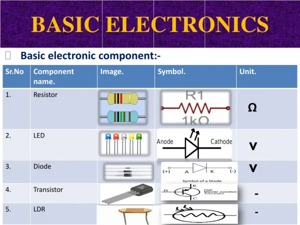
CONTENTS Resistor Capacitor Diode Transistor
Resistor • A resistor is a two-terminal passive electronic component. It is an electrical component that limits or regulates the flow of electrical current in an electronic circuit. Resistors can also be used to provide a specific voltage for an active device such as a transistor. • Symbol:
S.I unit is ohm • Symbol of ohm (Ω) • Notation for resistance O- for ohm K- for kilo ohm M- for mega ohm
Types of resistor 1. Fixed type resistor 2. Variable type resistor
Combination of resistor • series combination • parallel combination
Conti…… • Series combination
CONTI…. • In series the current remains same • In parallel the voltage remains same
Ohms law • Ohm's law states that the current through a conductor between two points is directly proportional to the potential difference across the two points, and inversely proportional to the resistance between them. • The mathematical equation that describes this relationship is:
Why we use resistor? • Limiting of current • Limiting of voltage • Power dissipation
A capacitor is a device for storing electric charge • A capacitor is a passive electronic component consisting of a pair of conductors separated by a dielectric (insulator).
CAPACITANCE • This is a measure of a capacitor's ability to store charge. • A large capacitance means that more charge can be stored. • Capacitance can be measured using formula: q = C V where C = capacitance, q= charge, V = potential difference. • Unit of Capacitance is Farads(F).
Combination of capacitors • Series combination • Parallel combination
Series combination • When capacitors are connected in series, the capacitance decreases. • In Series, total capacitance is given by the formula: 1/Ct= 1/C1+1/C2+………
Parallel combination • When capacitors are connected in parallel, the capacitance increases. • In Parallel, total capacitance is given by the formula: Ct= C1+ C2+………Cn
Types of capacitor • Polarized capacitor • Non polarized capacitor
Non Polarized capacitor • The capacitor which do not have a polarity
Polarised capacitor • The capacitor which have a polarity
Features • Capacitor offers low impedance to AC. • It offers high impedance to DC. • Reactance of capacitor is given by: Xc =1/2π fc where π =22/7
Applications • Blocking DC Voltage • Adjusting Frequency • Use to generate a time delay application • Smoothing of dc voltage.
Diode • Diode is an electronic component which permits the flow of current in one direction only. • Today diodes are made up of semiconductor material, therefore they are often called semiconductor diodes or crystal diodes.
Why we use it? • Diodes are used for rectification. • Diodes are used in electrical meters for there protection. • Diodes are used in wave shaping circuits. • Diodes (LED) are used in display.
Material • Diodes are semiconductor devices. • Silicon(Si) or germanium(Ge) are used.
Types • PN junction diode • Zener Diode • Light Emitting Diodes (LED) • Photo Diodes
PN Junction Diode • This diode is made by p-type & n-type material. • This PN junction diode works in forward bias i.e. anode is connected to positive terminal & cathode is connected to negative terminal.
How can we recognize? • There is a silver band on the one side of diode which is cathode (negative) terminal of the diode & the other side is anode (positive) terminal.
Zener Diode • Zener Diode works in reverse bias. • Symbol of zener diode:
How can we recognize zener a diode? • There is black band which is negative terminal & other one is positive terminal.
Light Emitting Diode (LED) • Light Emitting Diode (LED) operates in forward bias. • It emits light when connected in circuit. • Symbol of LED:
How can we recognize LED? • The shorter lead of the LED is negative terminal & longer one is positive, also on the negative terminal there is a flat spot when we see from the top.
Photo Diode • Often known as Photo detector. • Photo Diode operates in reverse bias. • Light falls on the PN junction of the photo diode which creates electron-hole pair in the depletion layer which causes flow of current. • Current depends upon the light intensity • When light incident on the photodiode then current flows in the circuit.
Working of Photodiode Photodiode
LDR(Light Dependent Resistor) • A light dependent resistor is a semiconductor electrical device that has a very high resistance to the flow of electrical current in t absence of light. • When light strikes the device, it lowers its resistance, allowing electrical current to flow through it and on to other devices or electrical circuits.
TRANSISTOR • A transistor is a semiconductor device used to amplify and switch electronic signals. It is made of a solid piece of semiconductor material, with at least three terminals for connection to an external circuit. • Device with three terminals where one terminal can be use to control the flow of current through the other two terminals.
Conti…. • The three terminals are Emitter, Base and Collector
Types of transistor • Junction transistor • Field effect transistor
Junction transistor • Transistor are of two types: 1-> n-p-n A straight switch 2-> p-n-p A inverted switch
n-p-n as a switch • When base of n-p-n is connected with logic high voltage then it short circuit emitter and collector (SWITCH ON). • When base of n-p-n is connected with logic low voltage then it open circuit both emitter and collector (SWITCH OFF).
Circuit diagram to show a switching VCC Logic 1 or RB Logic 0 M GND
p-n-p as an inverted switch • When base of p-n-p is connected with logic high voltage then it open circuit emitter and collector (SWITCH OFF). • When base of p-n-p is connected with logic low voltage then it short circuit both emitter and collector (SWITCH ON).