Basic Electronics
Basic Electronics. Basic Electronics. Three requirements of a complete circuit. Source of power Load Path. Basic Electronics. Millions of small charges called ELECTRONS move through the circuit. Basic Electronics.


Basic Electronics
E N D
Presentation Transcript
Basic Electronics Three requirements of a complete circuit • Source of power • Load • Path
Basic Electronics Millions of small charges called ELECTRONS move through the circuit.
Basic Electronics When the switch is closed the electrons flow through the wires from the battery, to the switch, to the lamp, and back to the battery.
Basic Electronics What charge is an electron? Negative Charge
Basic Electronics When the circuit is complete or closed electrons flow through the wires from NEGATIVE to POSITIVE.
Basic Electronics SWITCH provides a simple way to open and close a circuit
Basic Electronics Is a switch necessary to have a complete circuit? No
Basic Electronics SPST Switch – Single Pole Single Throw
Basic Electronics DPST Switch – Double Pole Single Throw
Basic Electronics Momentary Switch Switch is closed when the lever (red) is pushed down to make a complete circuit.
Basic Electronics Open Switch Closed Switch
Basic Electronics Wires Connected Wires Crossing (not connected)
Basic Electronics Lamp
Basic Electronics Speaker
Basic Electronics Capacitor (+) (-) • Electrons are stored inside the capacitor causing it to act like a battery • Capacitance is measured in microfarads
Basic Electronics Capacitor Insides • Plates are the conductors inside the capacitor. Electrons move around the plates causing a storage of energy that continues flowing even after all power has been disconnected. • Dielectric are the insulators inside the capacitor.
Basic Electronics Discharging capacitors Before working with a capacitor be sure it is discharged. Touch a probe to each capacitor terminal for discharge. Substituting capacitors Replace the capacitors with exact voltage rating. If impossible the voltage rating must be greater If a lower rating is used the circuit will result in damage.
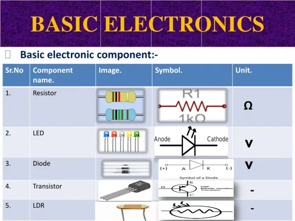
Basic Electronics Resistor (R): • Opposes the flow of current (I) • Can be used as a fuse in a circuit • R are not polarity sensitive • Measured in Ohms
Basic Electronics B Potentiometer (Pot): A C • Variable Resistor: opposes the flow of (I) • Designers use the pot to find the correct current (I) for a circuit • AB + BC = AC A B C
Basic Electronics Look at the photocell’s symbol & tell how the component operates. Photocell Squiggly lines mean: resistance: opposing the flow of (I) current Arrows pointing in means: the light comes from outside the component
Basic Electronics anode cathode (+) (-) Diode: One directional gate
Basic Electronics LED: Light Emitting Diode (+) (-) (-) short lead (+) long lead
Basic Electronics • Arrows pointing out means: light comes from the component • Component symbol in the middle means: one directional gate
Basic Electronics Cathode (-) Anode (+) Gate C A G SCR – Silicon Controlled Rectifier E to the gate turns the SCR on
Basic Electronics 3904 3906 PNP NPN Transistors amplification of signal
Basic Electronics 8 7 6 5 • 555 alternates from turning the voltage on and off • 555 produces a square wave at its output • Frequency is changed by the attached resistors and capacitor • Circle or dot on the IC marks pin ONE 1 2 3 4 1 8 2 7 3 6 4 5 555 Timer – IC – Intergraded Circuit
Basic Electronics Cell: AA/AAA Battery: two or more cells
Basic Electronics • If one resistor or component burns out the circuit will be open and not operational. • Total resistance = 1.2K + 100 + 360 • = 1660 ohms
Basic Electronics • Two or more paths for electrons to flow from a common voltage source • If one resistor burns out the other resistors will be closed & operational 1 Total resistance = 1/1.2K + 1/100 + 1/360 = 73.46 ohms
Standard Abbreviations Unit Measured in: I Current Amps (A) E Voltage Volts (V) R Resistance Ohms P Power Watts (W) F Frequency Hertz (Hz)