Download
1 / 14
140 likes | 252 Vues
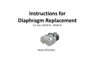
Instructions for Diaphragm Replacement Cat. Nos. 2052B-01, 2054B-01. Model 2052/2054. Kit for cat. no. 2052B-01 and 2054B-01 (4 head pumps). Kit part no. 402042-US.

E N D
Instructions for Diaphragm ReplacementCat. Nos. 2052B-01, 2054B-01 Model 2052/2054
Kit for cat. no. 2052B-01 and 2054B-01(4 head pumps) Kit part no. 402042-US
1. Loosen four bolts using 4 mm Allen Wrench(Although the photo shows a 2 head pump, a the procedure for a 4 head pump (Model 2052/2054) is the same.
2. Remove connection head and remove two valves and two o-rings
6. Using spanner(part no 826801-16) to loosen PTFE coated diaphragm holding plate(tightening washer) and do final loosening by hand to remove diaphragm and washer
7. Upon removal of:- diaphragm support plate (pressure washer), - diaphragm and - diaphragm holding plate (tightening washer) the connecting rod becomes visible
4. Assembly together diaphragm support plate(pressure washer), new diaphragm and tightening washer (diaphragm holding plate)
5. Use spanner to diaphragm holding plate(tighten washer). Make snug. Alert! - Allow 3 Hrs for loctite 242 to set before turning on pump.
6. Intake Stage. Place PEEK valves on plates as indicated with “shiny” side of valves facing down. Alert – important to have “shiny” side DOWN to reach vacuum level. Align pin and hole when assembling
7. Repeat steps 2 thru 6 on the Exhaust Stage of pump. Place PEEK valves on plates as indicated with “shiny” side of valve facing down. Alert – important to have “shiny” side DOWN to reach vacuum level. Align hole & pin when assembling
9. Insert teflon tubing into fitting on head and hand tighten plastic compression nut. Thread 4 bolts to secure heads. Snug tight the 4 bolts. Snug tight the plastic compression nut with 14 mm wrench.