Download
1 / 43
470 likes | 758 Vues
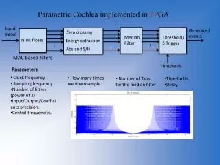
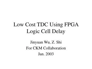
A Low-Power Wave Union TDC Implemented in FPGA. Wu, Jinyuan Fermilab Yanchen Shi and Douglas Zhu Illinois Mathematics and Science Academy Sept. 2011. Performance Degrading in CPU/GPU, ASIC & FPGA. Performance. Theoretical limit of current technology. Degrading Due to Design.

E N D
A Low-Power Wave Union TDC Implemented in FPGA Wu, Jinyuan Fermilab Yanchen Shi and Douglas Zhu Illinois Mathematics and Science Academy Sept. 2011
Performance Degrading in CPU/GPU, ASIC & FPGA Performance Theoretical limit of current technology Degrading Due to Design Carefully designed FPGA may have better performance than typical ASIC. Theoretical limit of Older technology Degrading Due to Structure Degrading Due to Design Degrading Due to Design CPU/GPU ASIC. FPGA • Imperfect designs degrade performance of ICs, including CPU/GPU considerably. • ASIC devices are built using older technology and suffering similar design degrading. • FPGA internal structure causes extra performance degrading in addition to design degrading. • Design modification in FPGA is easier so that design degrading can be minimized. A Low-Power Wave Union TDC Implemented in FPGA
Introduction • A 32-channel Wave Union TDC firmware has been implemented in an Altera Cyclone III FPGA device (EP3C25F324C6N, $73.90) and has been tested on a Cyclone III evaluation card. • Low-power design practice has been applied for applications in vacuum. • Time measurement function is tested on 16 channels and typical delta t RMS resolution between two channels is 25-30 ps. • Power consumption is measured for 32 channels at ~27 mW/channel. A Low-Power Wave Union TDC Implemented in FPGA
The Wave Union TDC Implemented in FPGA A Low-Power Wave Union TDC Implemented in FPGA
TDC Using FPGA Logic Chain Delay • This scheme uses current FPGA technology • Low cost chip family can be used. (e.g. EP2C8T144C6 $31.68) • Fine TDC precision can be implemented in slow devices (e.g., 20 ps in a 400 MHz chip). IN CLK A Low-Power Wave Union TDC Implemented in FPGA
Two Major Issues In a Free Operating FPGA • Widths of bins are different and varies with supply voltage and temperature. • Some bins are ultra-wide due to LAB boundary crossing A Low-Power Wave Union TDC Implemented in FPGA
Auto Calibration Using Histogram Method • It provides a bin-by-bin calibration at certain temperature. • It is a turn-key solution (bin in, ps out) • It is semi-continuous (auto update LUT every 16K events) 16K Events DNL Histogram S LUT In (bin) Out (ps) A Low-Power Wave Union TDC Implemented in FPGA
Good, However • Auto calibration solved some problems • However, it won’t eliminate the ultra-wide bins A Low-Power Wave Union TDC Implemented in FPGA
Wave Union TDC records multiple transitions. Wave Union Launcher A Regular TDC records only one transition Wave Union Launcher A 0: Hold 1: Unleash In CLK A Low-Power Wave Union TDC Implemented in FPGA
Wave Union Launcher A: 2 Measurements/hit 1: Unleash A Low-Power Wave Union TDC Implemented in FPGA
1 2 Sub-dividing Ultra-wide Bins 1: Unleash Device: EP2C8T144C6 • Plain TDC: • Max. bin width: 160 ps. • Average bin width: 60 ps. • Wave Union TDC A: • Max. bin width: 65 ps. • Average bin width: 30 ps. 1 2 A Low-Power Wave Union TDC Implemented in FPGA
Low-power Design Practices A Low-Power Wave Union TDC Implemented in FPGA
Low-Power Design Practice: Wave Union • Intrinsically the Wave Union TDC is a low-power scheme. • Multiple measurements are made with one set of delay line, register encoder etc. yielding finer resolution that otherwise needs several regular TDC blocks to achieve. A Low-Power Wave Union TDC Implemented in FPGA
Low-Power Design Practice: Clock Speed 250 MHz 62.5 MHz IN0 Delay Line & Sampling Register Array Data Load/ Transfer Register Encoder Buffer w/ Zero Suppression CK250 CK62 Load Clock Disable Sequencer • The Sampling Register Arrays are clocked at 250 MHz. • All other stages are clocked at 62.5 MHz. • When a valid hit is sampled, the Sampling Register Array is disabled so that the registered pattern is stable for 64 ns. • The Data Load/Transfer Registers are enabled to load input 64 ns, so that a valid hit is guaranteed to be load once and only once. A Low-Power Wave Union TDC Implemented in FPGA
Low Power Design Practice: Resource Sharing IN3 • The Data Load/Transfer Registers are enabled to load input 64 ns, (i.e., 4 clock cycles at 62.5 MHz). • The Data Load/Transfer Registers transfer data from other channels when they are not enabled to load. • Four channels share an Encoder and a Buffer with Zero Suppression. IN2 IN1 IN0 Delay Line & Sampling Register Array Data Load/ Transfer Register Encoder Buffer w/ Zero Suppression Data Merging Register CK250 CK62 Load Clock Disable Sequencer A Low-Power Wave Union TDC Implemented in FPGA
Block Diagram of 16 Channels 8B10B + Serialization TDC + Encoder Automatic Calibration Output Buffer Data Buffer + Concentration • The hit time for each of the 16 channel inputs is digitized and encoded. • Data from 4 channels are buffered and data from 4 groups of 4 channels are merged together. • Raw hit times are converted to fine time through automatic calibration block. • Data from all 16 channels are buffered and sent out via 4 pairs of LVDS ports @250 M bits/s. A Low-Power Wave Union TDC Implemented in FPGA
Test Results A Low-Power Wave Union TDC Implemented in FPGA
The Test Hardware www.altera.com A Low-Power Wave Union TDC Implemented in FPGA
Test Setup TDC Module NIM to LVDS Converter A Low-Power Wave Union TDC Implemented in FPGA
Output Raw Data and Typical Delta T Histogram Between Two Channels 00003C C064A6 F064B8 C07CA4 F07CB4 C094A0 F094B0 C0AC9C F0ACAC C0C497 F0C4A8 C0DC91 F0DCA2 • RMS of this histogram is 25 ps. A Low-Power Wave Union TDC Implemented in FPGA
Delta T Between NIM Inputs FPGA Pulse Gen. TDC LeCroy 429A NIM FAN- OUT NIM To LVDS A TDC B TDC TDC C LeCroy 429A NIM FAN- OUT NIM To LVDS TDC TDC TDC TDC • TDC channels internally ganged together has smallest standard deviation of time differences. • Typical channel pairs sharing same fan-out unit has 30 ps RMS. • Timing jitters of the fan-out units add to the measurement errors. A Low-Power Wave Union TDC Implemented in FPGA
Time Measurement Errors Due to Power Supply Noise Switching Power Supply Linear Power Supply • Typical RMS resolution is 25-30 ps. • Measurements with cleaner power (diamonds) is better than noisy power (squares). A Low-Power Wave Union TDC Implemented in FPGA
Specifications A Low-Power Wave Union TDC Implemented in FPGA
Other Applications: Single Slope ADC 4xR2 FPGA VIN1+ TDC VIN1- VIN2+ TDC VIN2- 4xR2 R R C VREF+ R1 VREF- A Low-Power Wave Union TDC Implemented in FPGA
If You Want to Try www.altera.com THDB-H2G (HSMC to GPIO Daughter Board) $50 www.altera.com DK-START-3C25N Cyclone III FPGA Starter Kit $211 • The FPGA on the Starter Kit is fairly powerful. • More than 16 pairs LVDS I/O can be accessed via the daughter card. • FPGA can fit 32 channels but implementing 16 channels is more practical given the I/O pairs. • TDC data are stored in the RAM on the board and can be readout via USB. • A good solution for small experiment systems as well as student labs. A Low-Power Wave Union TDC Implemented in FPGA
The End Thanks
Timing Uncertainty Confinement A Low-Power Wave Union TDC Implemented in FPGA
Historical Implementation in ASIC TDC DLL Clock Chain Coarse Time Counter c0 c1 HIT is used as CK input which creates unnecessary challenges. Coarse Time Register HIT Encoder Coarse Time Selection Logic Unnecessary Challenges = Extra Efforts + Reduced Performance • Deadtime is unavoidable. • Coarse time recording needs special care. • Two array + encoder sets are needed for raising edge and falling edge. • The register array must be reset for next event. • The encoder must be re-synchronized with system clock in order to interface with readout stage. A Low-Power Wave Union TDC Implemented in FPGA
Unnecessary Challenges Unnecessary for FPGA TDC 000 001 011 010 110 111 101 100 Gray Code Counter Coarse Time Counter Coarse Time Counter Coarse Time Counter • In history, Gray code counters, double counters and dual registers + MUX are found in ASIC TDC coarse time counter schemes. • Theses are unnecessary if the TDC is designed appropriately. • In FPGA, a plain binary counter is sufficient. A Low-Power Wave Union TDC Implemented in FPGA
A Better Implementation DLL Clock Chain HIT is used as D input. HIT Multi- Sampling Register Array Clock Domain Transfer 16-bit Encoder with Registered Outputs 16-bit Encoder with Registered Outputs Coarse Time Counter OR + Register DV EG T4..T0 TC • Deadtimeless operation is possible. • No special care is needed for coarse time. • Both raising and falling edges are digitized with a single array + encoder set. • No resetting is needed for the register array. • The output is synchronized with the system clock and is ready to interface with readout stage. A Low-Power Wave Union TDC Implemented in FPGA
Coarse Time Counter Coarse Time Counter Coarse Time HIT Fine Time Encoder Fine Time ENA • The timing uncertainty between HIT and CLK is confined in the sampling register array. • All the remaining logics are driven by the CLK signal. • No special cares such as Gray code counter is needed for coarse time counter. CLK Hit Detect Logic Data Valid A Low-Power Wave Union TDC Implemented in FPGA
Comparison A Low-Power Wave Union TDC Implemented in FPGA
More Measurements • Two measurements are better than one. • Let’s try 16 measurements? A Low-Power Wave Union TDC Implemented in FPGA
VCCINT =1.20V VCCINT =1.18V Wave Union Launcher B: 16 Measurements/hit 1 Hit 16 Measurements @ 400 MHz A Low-Power Wave Union TDC Implemented in FPGA
Delay Correction The raw data contains: • U-Type Jumps: [48-63][16-31] • V-Type Jumps: other small jumps. • W-Type Jumps: [16-31][48-63] Delay Correction Process: • Raw hits TN(m) in bins are first calibrated into TM(m) in picoseconds. • Jumps are compensated for in FPGA so that TM(m) become T0(m) which have a same value for each hit. • Take average of T0(m) to get better resolution. The processes are all done in FPGA. A Low-Power Wave Union TDC Implemented in FPGA
Test ResultNIM Inputs RMS 10ps 140ps 0 1 2 Wave Union TDC B BNC adapters to add delays @ 140ps step. Wave Union TDC B + NIM/ LVDS Wave Union TDC B Wave Union TDC B - LeCroy 429A NIM Fan-out Wave Union TDC B NIM/ LVDS Wave Union TDC B + Wave Union TDC B A Low-Power Wave Union TDC Implemented in FPGA Wave Union TDC B
A Preferable Scheme DLL Clock Chain c0 c1 c16 c17 HIT Multi- Sampling Register Array Clock Domain Transfer Coarse Time Counter 32-bit Encoder with Registered Outputs • Minimum setup time between the multi-sampling register array stage and the clock domain transfer stage: 17 clock taps. • Setup time between the clock domain transfer stage and the encoder register: 32 or 16 clock taps. • All outputs including TC are aligned with c0. • Supports both raising and falling edges. DV EG T4..T0 TC • EG: Edge, =1: Raising or =0: Falling. • T4..T0: Time. • DV: Data Valid, =1 Valid edge detected. • It is used as PUSH signal for FIFO or • Write Enable for other memory buffers. A Low-Power Wave Union TDC Implemented in FPGA
Low Power Design Practice: Clock Speed IN3 • The Sampling Register Arrays are clocked at 250 MHz. • All other stages are clocked at 62.5 MHz. • When a valid hit is sampled, the Sampling Register Array is disabled for 64 ns. • The Data Load/Transfer Registers are enabled to load input 64 ns, so that a valid hit is guaranteed to be load once and only once. • The Data Load/Transfer Registers transfer data from other channels when they are not enabled to load. • Four channels share an Encoder and a Buffer with Zero Suppression. IN2 IN1 IN0 Delay Line & Sampling Register Array Data Load/ Transfer Register Encoder Buffer w/ Zero Suppression CK250 CK62 Load Clock Disable Sequencer A Low-Power Wave Union TDC Implemented in FPGA
Test Setup TDC + Encoder • The hit time for each of the 16 channel inputs is digitized and encoded. • Data from 4 channels are buffered and data from 4 groups of 4 channels are merged together. • Raw hit times are converted to fine time through automatic calibration block. • Data from all 16 channels are buffered and sent out via 4 pairs of LVDS ports @250 M bits/s. A Low-Power Wave Union TDC Implemented in FPGA
Test Setup TDC + Encoder • The hit time for each of the 16 channel inputs is digitized and encoded. • Data from 4 channels are buffered and data from 4 groups of 4 channels are merged together. • Raw hit times are converted to fine time through automatic calibration block. • Data from all 16 channels are buffered and sent out via 4 pairs of LVDS ports @250 M bits/s. A Low-Power Wave Union TDC Implemented in FPGA
Wave Union Launcher B Wave Union Launcher B 0: Hold 1: Oscillate In CLK A Low-Power Wave Union TDC Implemented in FPGA
Cell Delay-Based TDC + Wave Union Launcher The wave union launcher creates multiple logic transitions after receiving a input logic step. The wave union launchers can be classified into two types: • Finite Step Response (FSR) • Infinite Step Response (ISR) This is similar as filter or other linear system classifications: • Finite Impulse Response (FIR) • Infinite Impulse Response (IIR) Wave Union Launcher In CLK A Low-Power Wave Union TDC Implemented in FPGA
Wave Union? Photograph: Qi Ji, 2010 A Low-Power Wave Union TDC Implemented in FPGA