Download
1 / 1
30 likes | 282 Vues
Thermo-Mechanical Finite Element Analysis of an HTS Current Lead by Means of ANSYS. James D. McClain Haverford College, Department of Chemistry, Haverford, PA 39041.

E N D
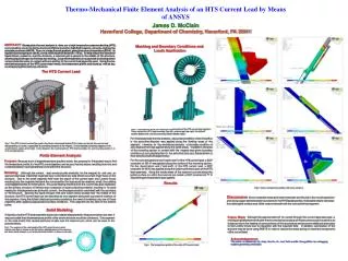
Thermo-Mechanical Finite Element Analysis of an HTS Current Lead by Means of ANSYS James D. McClain Haverford College, Department of Chemistry, Haverford, PA 39041 ABSTRACT:Steady-state thermal analysis is done on a high temperature superconducting (HTS) current lead for use in the Series Connected Hybrid and other high-field magnets, using the engineering simulation software ANSYS. There is a large thermal gradient, going from room temperature (300 K) to liquid helium temperature (4.5 K), over a relatively short distance (~1.6 m). To help reduce the amount of liquid helium needed to cool the structure, a reservoir pot is placed in the middle of the structure, allowing liquid nitrogen to eliminate any heating. Large thermal strains are suspected to develop where various materials come in contact with one another in the current lead presently used. Using thermo-mechanical analysis of the HTS current lead model, the temperature profile was found as well as any accompanying thermal stress and strain. Meshing and Boundary Conditions and Loads Application The HTS Current Lead Total strain intensity Fig.3. These pictures show the meshing of various parts of the HTS current lead segment. These include the HTS lead assembly (top left), reservoir pot (top right), the jellyroll section (bottom left), and the mounting section (bottom right). For the steady-state thermal analysis, a boundary condition of zero heat flux in the azimuthal direction was applied along the flanking areas of the segment. Likewise, for the mechanical analysis, a boundary condition of zero displacement was applied along the same areas. In addition, the area of the mounting section in contact with the magnet was given boundary conditions of zero displacement in the azimuthal and zero displacement in the z-direction (cylindrical geometry). For the room temperature end (“warm end”) of the HTS current lead, a DOF constraint of 300 K was applied along the surface of the mounting section. For the liquid helium end (“cold end”) of the HTS current lead, a DOF constraint of 4.5 K was applied along the bottom cylindrical area of the HTS lead assembly. Along the inside areas of the reservoir pot and along the bottom surface on which the reservoir pot rested, a DOF constraint of 77 K (liquid nitrogen temperature) was applied. Fig.1. The HTS Current Lead will be used in the Series Connected Hybrid (SCH) shown on the left (the current lead designated by an arrow), responsible for providing electricity to the magnet. A more detailed schematic diagram of the current lead is shown on the right. In this diagram, the reservoir pot (2), HTS lead assembly (3), and mounting section (1, 4, 5, 6) are pointed out. Finite Element Analysis Purpose: Because such a large temperature gradient exists, the purpose for this project was to find the temperature profile for the HTS current lead as well as any thermal strains resulting from this and contacts between varying materials found within the structure. Modeling:Although the current lead would provide electricity for the magnet for real use, an approximation was made that neglected any current and any side effects a current might have on the structure. Due to the small magnetic field near the region of the current lead, any Lorentz forces resulting from the magnetic field and the current within the lead would be relatively small, thus adding only negligible stress to the structure. Any joule heating resulting from the current was also neglected, as the primary structure of interest was composed of superconducting material, resulting in no joule heating for that segment even at the full current. Another approximation used dealt with the symmetry of the structure. Ignoring the liquid nitrogen inlet and outlet valves located near the middle of the structure, the HTS current lead can be described as one segment along with successive rotations of this segment. Using this 5-fold rotational symmetry resulted in the need of modeling only one of those segments after applying appropriate boundary conditions. This segment can be seen in the section below. Results Fig.5. Various temperature profiles and stress analysis. Discussion:Some moderate stress and strain intensities were found in the mounting section and along copper-stainless steel boundaries in the HTS lead assembly. Noticeable strains were also found along the contact area of the reservoir sheath with the main cylindrical segment. Solid Modeling Originally only the HTS lead assembly was to be modeled (designated in the picture below), but later it was concluded that the temperature profile of the whole structure would be of interest. One segment of the solid model that caused particular trouble was the reservoir pot, which can be seen in the pictures below. Future Work: Although the approximation of no current through the current lead was used, a more appropriate treatment for the thermo-mechanical analysis of the structure would include this as it plays a role in the heating of some portions of the structure as well as some additional stress due to the Lorentz forces due to interaction with the magnetic field. In addition, optimization of the structure may be done using ANSYS in order to reduce the stress acting on important components of the current lead. Fig.2. The segment of the solid model of the HTS current lead on which analysis was done is shown on the left while a detailed picture of the reservoir pot, where liquid nitrogen is run to help eliminate heating, is shown on the right. Acknowledgements: The author is indebted to Dr. Andy Gavrilin, Dr. Jack Toth and Mr. George Miller for unflagging support, great help, and insight. Fig.4. The temperature profile of the entire HTS current lead.