Download

1 / 22
730 likes | 2.36k Vues
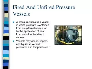
Pressure Vessels and Shrink Fits. Thin-Walled Pressure Vessels. If the wall thickness is = < 1/10 the inner radius, the vessel may be considered thin-walled. In thin walled pressure vessels, the inner and outer radii are set equal to r , and the thickness is t . Thin-Walled Pressure Vessels.

E N D
Thin-Walled Pressure Vessels • If the wall thickness is = < 1/10 the inner radius, the vessel may be considered thin-walled. • In thin walled pressure vessels, the inner and outer radii are set equal to r, and the thickness is t.
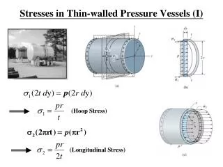
Thin-Walled Pressure Vessels The stress is assumed to be uniform throughout the thickness. Usually only two stress components are significant, axial and tangential.
Thin-Walled Stresses (Review) • Axial, or longitudinal stress, is • Circumferential, or tangential stress, is (also for a sphere)
Thin-Walled Stresses (Review) Stress in the radial direction, r, varies from -p (p = pressure) at the interior of the vessel to zero at the exterior (for internally pressurized vessels). r is usually << than either or a, and is usually neglected.
Thick-Walled Pressure Vessels • Thick-walled vessels often operate under much higher pressures than thin-walled, and the radial stress component cannot usually be ignored. • Stresses vary through the wall thickness, unlike the assumption for thin-walled vessels.
Thick-Walled Nomenclature a = inside radius b = outside radius r = arbitrary radius u = radial displacement pi = inside pressure po = outside pressure r = radial stress = tangential stress z = axial stress
Thick-Walled, Internal Pressure (po = 0) is > r. Note variation with r.
Thick-Walled, Internal Pressure Notes: r is always compressive; max. at r = a. (max at i.d.) is always tensile, also max. at r = a.
Thick-Walled, External Pressure Notes: r is always compressive; max. at r = b. (max. at o.d.) is also compressive, max. at r = a.
Thick-Walled, Axial (or Longitudinal) Stress z = (pia2 – pob2)/(b2 – a2) (For either internal or external pressure)
Uses for Thick-Walled Equations • Use is for high pressures in a thick walled vessel. Straightforward application of formulas. • A second use is in the calculation of shrink fits, either for assembly or to create very strong composite structures. In these cases, the contact pressure p between the parts, is treated as po or pi in the preceding equations.
Determining Contact Pressure, p In many cases, the designer may choose a maximum tangential stress . Then, p may be solved for (as pi for the hub) using Watch your a’s, b’s, and c’s!
Determining Contact Pressure, p Otherwise, the designer may choose to specify an interference , or the contact pressure p itself and then solve for the necessary to achieve that p.
Contact Pressure If the hub & shaft are of the same material, this condenses to:
Shrink Fits Once p is determined, assume a friction factor f : usually 0.15 < f < .20. The assembly force F to assemble a shrink-fit assembly is given by Eq.: F = 2bpfL, where L is the length of the fit. Holding Torque T is given by: T = Fb = 2b2fpL
Press Fit, Example: Steel Shaft Press Fit Onto Cast Fe Disc a = 25mm b = 50 mm c = 125 mm L = 100 mm Es = 210 Gpa s = .3 Eh = 70 Gpa h = .25 Assumptions: max. tangential stress NTX 30 MPa, contact pressure is uniform, and f = 0.15. FIND: radial interference , assembly force, & torque capacity.
Flywheels A flywheel is a typically a disc which rotates on a shaft. They are used to smooth out small oscillations and to store energy (kinetic energy of rotation). Examples: cars, hybrids, punch press
Flywheels • Design and analysis is similar to what we have covered. An added component is consideration of the radial forces developed by the rotation – a term of 2 is introduced.