Pressure Vessels
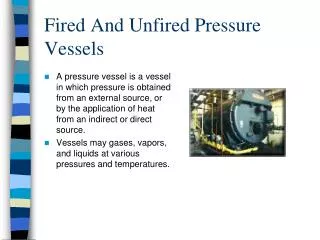
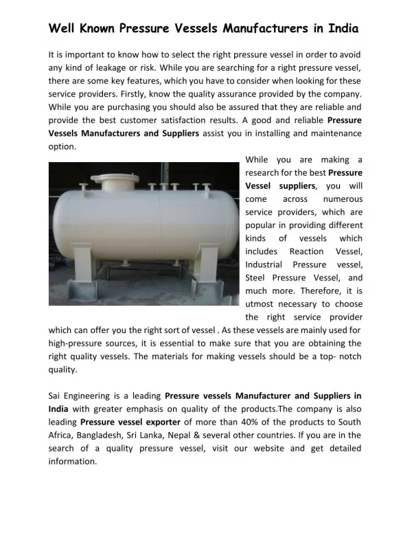
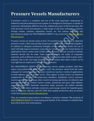
Pressure Vessels. A Pressure Vessel is a container for fluids under pressure between 15 psig to 3000 psig ASME Boilers and Pressure vessel Code Section VIII Division I sets rules for the design, fabrication, and inspection of pressure vessels. Main PV Components and Configurations.

Pressure Vessels
E N D
Presentation Transcript
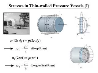
A Pressure Vessel is a container for fluids under pressure between 15 psig to 3000 psig • ASME Boilers and Pressure vessel Code Section VIII Division I sets rules for the design, fabrication, and inspection of pressure vessels
Main PV Components and Configurations The shell is the primary component that contains the pressure. Curved shape Vessel may be cylindrical, spherical, or conical The Vessel is always closed by heads The components are typically welded together
Main PV Components and Configurations Multiple diameters, thicknesses or materials are possible The Saddle supports used for horizontal drums (1) Spreads load over shell; (2) One support is fixed, the other slides
Main PV Components and Configurations Most heads are curved shape for strength, thinness, and economy Semi-elliptical shape is most common head shape
Main PV Components and Configurations Small vertical drums typically supported by legs > Typically max 2:1 ratio of leg length to diameter > Number, size, and attachment details depend on loads
Main PV Components and Configurations Nozzles used for: > Piping systems > Instrument Connection > Manways > Attaching other equipments Ends are typically flanged, may be welded
Main PV Components and Configurations Skirt Supports typically used for tall vertical vessels GENERAL support design > Designed for weight, wind, earthquake > Pressure is not a factor > Temperature is also a consideration for material selection and thermal expansion
Main PV Components and Configurations Spherical storage vessels are typically supported on legs Cross- bracing is typically used to absorb wind and earthquake loads
Main PV Components and Configurations Vessel size limits for lug support: > 1 to 10 ft diameter > 2:1 to 5:1 height to diameter ratio Lugs are bolted to horizontal structure
MATERIAL SELECTION Material Selection Factors: > Strength > Corrosion Resistance > Resistance to Hydrogen Attack > Fracture Toughness > Fabricability
MATERIAL SELECTION FACTORS Strength – mat’ls ability to withstand imposed loading Determines req’d component thickness Overall strength determined by: > Yield Strength > Ultimate Tensile Strength > Creep Strength > Rupture Strength
MATERIAL SELECTION FACTORS Corrosion Resistance – Deterioration of metal by chemical action MOST IMPORTANT factor to consider Corrosion allowance supplies additional thickness Alloying elements provide additional resistance to corrosion
MATERIAL SELECTION FACTORS Resistance to Hydrogen Attack At 300 – 400 ⁰F, monoatomic hydrogen forms molecular hydrogen in voids Pressure buildup can cause steel to crack Above 600 ⁰F, hydrogen attack causes irreparable damage through component thickness Increased alloy content (i.e. Cr) increase H2 attack resistance
MATERIAL SELECTION FACTORS Brittle Fracture and Fracture Toughness Fracture toughness – ability of mat’l to withstand cond’ns that cause brittle fracture Brittle fracture > Typically at “low” temperature > Can occur below design pressure > No yielding before complete failure
MATERIAL SELECTION FACTORS Brittle Fracture and Fracture Toughness Conditions for Brittle Fracture to Occur: > High enough stress for crack initiation and growth > Low enough mat’l fracture toughness at temperature > Critical size defect to act as stress concentration Brittle Fracture occurs w/o warning and is catastrophic
MATERIAL SELECTION FACTORS Brittle Fracture and Fracture Toughness Fracture Toughness Varies with: > Temperature > Type and Chemistry of steel > Manufacturing and Fabrication processes > Arc strikes, esp. if over repaired area > Stress raisers or scratches in cold formed thick plate
MATERIAL SELECTION FACTORS Brittle Fracture and Fracture Toughness • Simplified ASME Evaluation Approach • Material specification classified into Material Groups A to D • Impact test exemption curves • For each material group • Acceptable MDMT vs. thickness where impact testing not required • > If combination of Material Group and thickness not exempt, then must impact test at CET
MATERIAL SELECTION FACTORS Brittle Fracture and Fracture Toughness • Additional ASME Code Impact Test Requirements • Required for welded construction over 4 in. thick, or non-welded construction over 6in. thick, if MDMT < 120 F • Not Required for Flanges if temperature ≥ -20 F • MDMT reduction if calculated stress < allowable stress
MATERIAL SELECTION FACTORS Fabricability Ease of Construction Any required special fabrication practices Material must be weldable