PRESSURE VESSELS
PRESSURE VESSELS. DESIGN PROCEDURES. Engr. Butch G. Bataller ChE 192 Process Equipment Design September 20, 2011 . Pressure Vessels. Closed vessel having an internal pressure between 15 psig to 3000 psig

PRESSURE VESSELS
E N D
Presentation Transcript
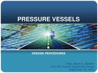
PRESSURE VESSELS DESIGN PROCEDURES Engr. Butch G. Bataller ChE 192 Process Equipment Design September 20, 2011
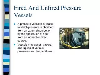
Pressure Vessels • Closed vessel having an internal pressure between 15 psig to 3000 psig • ASME Boiler and Pressure Vessel Code contains rules for the design, fabrication and inspection of boilers and pressure vessels • May include reflux drum, storage tanks, heat exchangers, chemical reactors, distillation columns, absorption tower, stripping columns, etc.
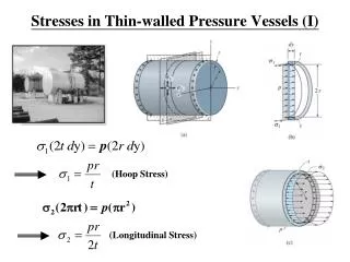
PV Design: Shell Thickness • In general, the minimum wall thickness of welded metal plates subject to pressure, excluding corrosion allowances, should not be less than 2.4 mm • a function of the ultimate tensile strength of the metal at operating temperature, operating pressure, vessel diameter and welding joint efficiency
PV Design: Shell Thickness • For a cylinder based on Inside diameter where tp = shell thickness required (inch) [m] P = Internal design gauge pressure (psig) [kN/m2] R = Inside Radius (inch) [m] S = Allowable stress (psi) [kN/m2] E = Joint efficiency factor (Table 6-2) C = Corrosion allowance (inch) [m]
PV Design: Shell Thickness • For a cylinder based on Inside diameter • Provided that • tpless than or equal to or • Pressure is less than or equal to 0.385 SE (Jawad and Farr, 1988)
PV Design: Shell Thickness • For a cylinder based on Outside diameter where tp = shell thickness required (inch) [m] P = Internal gauge pressure (psig) [kN/m2] R = outside Radius (inch) [m] S = Allowable stress (psi) [kN/m2] E = Joint efficiency factor (Table 6-2) C = Corrosion allowance (inch) [m]
PV Design: Shell Thickness • Allowance for Vertical PV • For 10>( L/Di)2/ Pd>1.34: tv = tp[0.75 + 0.22E( L/Di)2/Pd] • If (L/Di)2/Pd < 1.34, tv=tp
PV Design: Shell Thickness • Corrosion Allowance • 1/8 inch for noncorrosive conditions • ¼ for corrosive environments. ts = tV + tc
PV Design: Shell Thickness • For Vacuum Vessels where Pc= Collapsing pressure (psi) Te = Thickness to withstand external pressure (inch) Do = Outside diameter (inch) Em = Material’s modulus of elasticity [Table 6-4] ** Temust be high enough so that Pc is five times greater than the difference between atmospheric pressure and design vacuum pressure
PV Design: Shell Thickness • For Vacuum Vessels (alternate) tE=1.3(PdL/EmDo)4 tEC=L(0.18Di-2.2 )x 10 -5- 0.19 tV = tE + tEC where Pd= internal design gauge pressure (psi) Te = Thickness to withstand external pressure (inch) Do = Outside diameter (inch) Em = Material’s modulus of elasticity
PV Design: Shell Thickness • Spherical Vessels where P = internal design gauge pressure (psig) R = Inside Radius (inch) tp= Minimum required thickness (inch) E = Lowest joint efficiency S = Max allowable stress (psi)
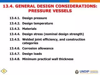
Design Temperature • design temperature may be equal to operating temperatueplus 50oF
Material of Construction • Carbon Steel >>> Non-corrosive environment, T= (-20 to 650 OF) • Low Alloy Steel >>> Non-corrosive environment, T= (650 to 900 OF) • Stainless Steel 300 Series >>> can be used up to 1,500 OF
Sample Problem Determine the thickness of a 5 meter inside diameter spherical tank for handling a corrosive liquid at a design pressure and temperature of 300KPa and 27F, respectively. The material of construction is made of carbon steel.
Sample Problem • If the height of the tank is 35m, what is the thickness of the tank incorporating earthquake and wind load? • What if the given pressure is an operating pressure?
Butt joint Corner joint Edge joint Lap joint T joint Types of Welded Joints
Square Butt Joints • Used to butt weld light sheet metal • 1/16 to 3/16 thick metal.
Beveled Butt Joints • Used to butt weld heavier pieces of metal together • 3/8 to ½ inch metal can welded using a single V or U joint • ½ Inch metal and up can be welded using a double V or U joint
Corner Joints • Used to join to pieces of metal that are approximately right angles to each other • Closed corner joint is used on light sheet metal were strength is not required at the joint • Half open corner joint is used on heavier metal when welding can only be done on one side. Used when load is not severe.
Corner Cont. • Open corner joint is used on heavy material. It is the strongest of the corner joints • Corner joints on heavy material are welded on both sides The outside first then reinforced on the inside
Edge Joints • Used to join two parallel or nearly parallel pieces of metal (0.25 in thick or less). Not very strong. • Used mainly to join edges of sheet metal, reinforce flanges of I beams, and mufflers.
Lap Joints • Used to join two overlapping pieces of metal • Single lap joint welded from one side • Single lap joint welded from two sides develops full strength • Off set lap joint is used when two pieces of metal need to be joined in the same plain.
Lap Joints Cont. • A- single lap joint, one weld. • B- single lap joint, two welds. • C- offset lap joint.
Tee Joints • Used to join two pieces of metal that are approximately 90 degrees to each other, but the surface of one piece of metal is not in the same plain as the other metal.
Tee Joints Cont. • A- plain tee • B- single beveled • C- double beveled • D- single J • E- double J
Types of Welds • Fillet weld- basic weld used. Used when joining two pieces of metal without preparing the surface of the metal first. • Groove weld- basic weld, used when preparing the metal before welding it into place.
Weld/Joint Efficiency Welding– heats the metal surrounding the welding area - results in warping, shrinking of the welded area Stress Relieving- required to release locked up localized stress - annealing or hammering Radiographing- locate weld defects and other structural trouble - welded joints are exposed to x-ray to detect excessive porosity, defective fusion and other defects in the welding process
Weld/Joint Efficiency • For carbon steels (t ≤ 1.25 in) • requires only 10% x-ray check • E = 85% • For thicker walls • requires 100% x-ray check • E = 100%
Weld/Joint Efficiency • Longitudinal joints should be butt- welded • Vessels in lethal application should be butt-welded and fully radiographed • All vessels fabricated on carbon or alloy steel requires post-heat treatment • All welded joints of cryogenic tanks must be butt welded, postweld heat treated and X- ray examined
For double butt joint, the following are the corresponding efficiencies Full radiography 100% Spot radiography 85% No radiography 70 % ** when welded joint efficiency is not known, assume a no spot radiography
Welded Joints Categories Category A – Longitudinal welded joints within main parts(shells, heads, cones, flat plates, nozzles, and the attachment weld of a hemispherical head to a shell)
Welded Joints Categories Catefory B – Circumferential welded joints within the main parts (shell, cone, nozzles and the attachment joint between formed heads (elliptical and torispherical) and shell).
Category C – welded joints connecting flanges, tubesheets, flat heads to main shell, to formed heads, to transition in diameter, to nozzles, or any welded joint connecting one side plate to another side plate of a flat-sided vessel Welded Joints Categories Category C – welded joints connecting flanges, tubesheets, flat heads to main shell, formed heads, transition in diameter, nozzles, or any welded joint connecting one side plate to another side plate of a flat-sided vessel
Category C – welded joints connecting flanges, tubesheets, flat heads to main shell, to formed heads, to transition in diameter, to nozzles, or any welded joint connecting one side plate to another side plate of a flat-sided vessel Welded Joints Categories Category D – welded joints connecting nozzles to main shells, spheres, formed heads, flat heads, flat-sided vessels.
Maximum Allowable Joint Efficiencies for Arc and Gas Welded Joints