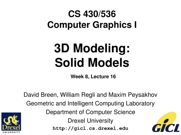
CS 430/585 Computer Graphics I 3D Representation and Solid Modeling Week 8, Lecture 15
460 likes | 678 Vues
CS 430/585 Computer Graphics I 3D Representation and Solid Modeling Week 8, Lecture 15. David Breen, William Regli and Maxim Peysakhov Geometric and Intelligent Computing Laboratory Department of Computer Science Drexel University http://gicl.cs.drexel.edu. Overview. 3D Modeling

CS 430/585 Computer Graphics I 3D Representation and Solid Modeling Week 8, Lecture 15
E N D
Presentation Transcript
CS 430/585Computer Graphics I3D Representation and Solid ModelingWeek 8, Lecture 15 David Breen, William Regli and Maxim Peysakhov Geometric and Intelligent Computing Laboratory Department of Computer Science Drexel University http://gicl.cs.drexel.edu
Overview • 3D Modeling • Wireframes • Surface Models • Solids and Solid Modeling • Sweep Representations • Constructive Solid Geometry • Boundary Representation 1994 Foley/VanDam/Finer/Huges/Phillips ICG
3D Modeling • 3D Representations • Wireframe models • Surface Models • Solid Models • Meshes and Polygon soups • Voxel/Volume models • Decomposition-based • Octrees, voxels • Modeling in 3D • Constructive Solid Geometry (CSG), Breps and feature-based
Exact Wireframe Parametric Surface Solid Model CSG BRep Implicit Solid Modeling Approximate Facet / Mesh Just surfaces Voxel Volume info Representing 3D Objects
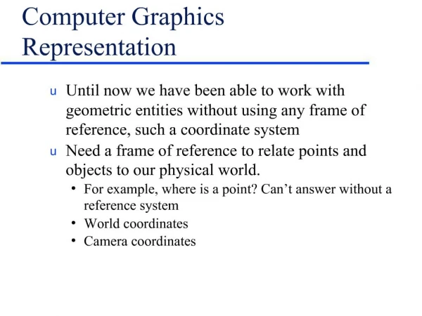
Exact Precise model of object topology Mathematically represent all geometry Approximate A discretization of the 3D object Use simple primitives to model topology and geometry Representing 3D Objects
Exact Complex data structures Expensive algorithms Wide variety of formats, each with subtle nuances Hard to acquire data Translation required for rendering Approximate Lossy Data structure sizes can get HUGE, if you want good fidelity Easy to break (i.e. cracks can appear) Not good for certain applications Lots of interpolation and guess work Negatives when Representing 3D Objects
Exact Precision Simulation, modeling, etc Lots of modeling environments Physical properties Many applications (tool path generation, motion, etc.) Compact Approximate Easy to implement Easy to acquire 3D scanner, CT Easy to render Direct mapping to the graphics pipeline Lots of algorithms Positives when Representing 3D Objects
Exact Representations • Wireframe • Parametric Surface • Solid Model • operations • CSG, BRep, implicit geometry
Wireframes • Basic idea: • Represent the model as the set of all of its edges • Example:A simple cube • 12 lines • 8 vertices • How about the faces? Foley/VanDam, 1990/1994
Wireframes: Examples • Cube with extra wires • Question: why would you want this? Foley/VanDam, 1990/1994
Issues with Wireframes • Visually ambiguous • No surfaces! • What’s inside? What’s outside? • Hidden line removal? • What does validity entail? • Don’t we just have a bunch of wires? • Do they need to add up to something? • How to model wireframe shapes? • Wire by wire? Not very easy!
Surface Models • Basic idea: • Represent a model as a set of faces/patches • Limitations: • Topological integrity; how do faces “line up”?; which way is ‘inside’/ ‘outside’? • Used in many CAD applications • Why? They are fine for drafting and rendering, not as good for creating true physical models
Surface Models: Examples • Utah Teapot • Original IGES standard • Bezier patches
Solids and Solid Modeling • Solid modeling introduces a mathematical theory of solid shape • Domain of objects • Set of operations on the domain of objects • Representation that is • Unambiguous • Accurate • Unique • Compact • Efficient
Solid Objects and Operations • Solids are point sets • Boundary and interior • Point sets can be operated on with boolean algebra (union, intersect, etc) Foley/VanDam, 1990/1994
Solid Object Definitions • Boundary points • Points where distance to the object and the object’s complement is zero • Interior points • All the other points in the object • Closure • Union of interior points and boundary points
Issues with 3D Set Operations • Ops on 3D objects can create “non-3D objects” or objects with non-uniform dimensions • Objects need to be “Regularized” • Take the closure of the interior Input set Closure Interior Regularized Foley/VanDam, 1990/1994
Regularized Boolean Operations • 3D Example • Two solids A and B • Intersection leaves a “dangling wall” • A 2D portion hanging off a 3D object • Closure of interior gives a uniform 3D result Pics/Math courtesy of Dave Mount @ UMD-CP
Boolean Operations • Other Examples: • (c) ordinary intersection • (d) regularized intersection • AB - objects on the same side • CD objects on different sides Foley/VanDam, 1990/1994
Boolean Operations Foley/VanDam, 1990/1994
Constructive Solid Geometry (CSG) • A tree structure combining primitives via regularized boolean operations • Primitives can be solids or half spaces
A Sequence of Boolean Operations • Boolean operations • Rigid transformations Pics/Math courtesy of Dave Mount @ UMD-CP
The Induced CSG Tree Pics/Math courtesy of Dave Mount @ UMD-CP
The Induced CSG Tree • Can also be represented as a directed acyclic graph (DAG) Pics/Math courtesy of Dave Mount @ UMD-CP
Issues with Constructive Solid Geometry • Non-uniqueness • Choice of primitives • How to handle more complex modeling? • Sculpted surfaces? Deformable objects?
Issues with Constructive Solid Geometry • Non-Uniqueness • There is more than one way to model the same artifact • Hard to tell if A and B are identical
Issues with CSG • Minor changes in primitive objects greatly affect outcomes • Shift up top solid face Foley/VanDam, 1990/1994
Uses of CSG Constructive Solid Geometry • Found (basically) in every CAD system • Elegant, conceptually and algorithmically appealing • Good for • Rendering, ray tracing, simulation • BRL CAD
Sweep Representations • An alternative way to represent 3D obj. • Idea • Given a primitive (e.g. polygon,sphere ) • And a sweep(e.g. vector, curve…) • Define solid as space swept out by primitive Foley/VanDam, 1990/1994
Sweep Representations • Issue: how to define intersection? Foley/VanDam, 1990/1994
CAD: Feature-Based Design • CSG is the basic machinery behind CAD features • Features are • Local modifications to object geom/topo with engineering significance • Often are additive or subtractive mods to shape • Hole, pocket, etc…
Parametric Modeling in CAD • Feature relationships • Constraints Foley/VanDam, 1990/1994
Boundary Representation Solid Modeling • The de facto standard for CAD since ~1987 • BReps integrated into CAGD surfaces + analytic surfaces + boolean modeling • Models are defined by their boundaries • Topological and geometric integrity constraints are enforced for the boundaries • Faces meet at shared edges, vertices are shared, etc.
Let’s Start Simple:Polyhedral Solid Modeling • Definition • Solid bounded by polygons whose edges are each a member of an even number of polygons • A 2-manifold: edges members of 2 polygons
Properties of 2-Manifolds • For any point on the boundary, its neighborhood is a topological 2D disk • If not a 2-manifold, neighborhood not a disk Foley/VanDam, 1990/1994
Euler’s Formula • For simple polyhedra (no holes):#Vertices - #Edges + #Faces = 2 Foley/VanDam, 1990/1994
Euler’s Formula (Generalized) #Vertices - #Edges + #Faces - #Holes_in_faces = 2 (#Components – Genus) • Genus is the # holes through the object • Euler Operators have been the basis of several modeling systems (Mantyla et al.) Foley/VanDam, 1990/1994
Euler Operators Loop L H, Shell S C
Steps to Creating a Polyhedral Solid Modeler • Representation • Points, Lines/Edges, Polygons • Modeling • Generalization of 3D clipping to non-convex polyhedra, enables implementation of booleans
State of the Art: BRep Solid Modeling • … but much more than polyhedra • Two main (commercial) alternatives • All NURBS, all the time • Pro/E, SDRC, … • Analytic surfaces + parametric surfaces + NURBS + …. all stitched together at edges • Parasolid, ACIS, …
BRep Data Structures • Winged-Edge Data Structure (Weiler) • Vertex • n edges • Edge • 2 vertices • 2 faces • Face • m edges Pics/Math courtesy of Dave Mount @ UMD-CP
BRep Data Structure • Vertex structure • X,Y,Z point • Pointers to n coincident edges • Edge structure • 2 pointers to end-point vertices • 2 pointers to adjacent faces • Pointer to next edge • Pointer to previous edge • Face structure • Pointers to m edges
Issues in Boundary Representation Solid Modeling • Very complex data structures • NURBS-based winged-edges, etc • Complex algorithms • manipulation, booleans, collision detection • Robustness • Integrity • Translation • Features • Constraints and Parametrics
Other Issues:Non-Manifold Solids • There are cases where you may need to model entities that are not entirely 3D Pics/Math courtesy of Dave Mount @ UMD-CP
Programming Assignment 5 • Extend XPM to 60 different RGB colors • Read 3 models and assign each a color • Implement Z-buffer rendering • Implement front & back cutting planes • Only render parts of models between planes • Implement linear depth-cueing • Color = base_color(z-far)/(near-far) • Re-use and extend 2D polygon filling