Sequential Circuit Design: FSM Mealy vs Moore Models
230 likes | 338 Vues
Learn about Finite State Machine (FSM) design using Mealy and Moore models for sequential circuits. Explore examples and differences between these models for effective digital system design.

Sequential Circuit Design: FSM Mealy vs Moore Models
E N D
Presentation Transcript
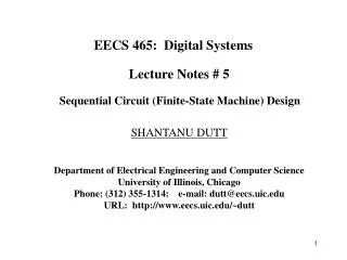
EECS 465: Digital Systems Lecture Notes # 5 Sequential Circuit (Finite-State Machine) Design SHANTANU DUTT Department of Electrical Engineering and Computer Science University of Illinois, Chicago Phone: (312) 355-1314: e-mail: dutt@eecs.uic.edu URL: http://www.eecs.uic.edu/~dutt
Finite State Machine (FSM) Design x O/p y FSM CLK • FSMs are different from counters in the sense that they have external I/Ps, and state transitions are dependent on these I/Ps and the current state. • Example : Problem Statement There is a bit-serial I/P line. Design an FSM that outputs a ‘0’ if an even # of 1’s have been received on the I/P line and the outputs a ‘1’ otherwise. Note : If a synchronous sequential circuit is being designed, the counting of the # of 1s occur every clock cycle. CLK x # of 1s even (0) odd (1) even (2) odd (3) odd (3)
• First determine the # of useful information classes required to solve the problem. • In this case, only 2 classes of information is required: whether an even # of 1s have been received, or an odd # of 1s have been received Solution 1: (Mealy) Solution 2: (Moore) 0 0/0 Reset Reset Even Even Input Output [0] 1/1 O/P is dependent on current state and input in Mealy 1/0 1 1 Input Output Odd Odd [1] Transition Arc Output is dependent only on current state 0 0/1 Mealy Machine: Output is associated with the state transition, and appears before the state transition is completed (by the next clock pulse). Moore Machine: Output is associated with the state and hence appears after the state transition take place.
External I/Ps Next State Comb. Logic External I/Ps External O/Ps m1 m1 Comb. Logic m2 FFs n n FFs Output Logic n n CLK External Outputs m2 CLK even odd Moore Machine Model Mealy Machine Model Time t : Even I/P = propagation delay of logic of Mealy M/C 2 = propagation delay of O/P logic unit of Moore M/C t+TCLK+2 t+ t+TCLK t Even x=1 O/P=0 Odd O/P=1 (Moore) O/P=1 (Mealy)
State Transition Table (Even-Parity Checker) Even State: 0 ; Odd State: 1; State Variable A Next State Present State Mealy O/P D-FF Excit. Moore O/P T-FF Excit. Input A x A+ y1 y2 DA TA 0 0 0 0 0 0 0 0 1 1 0 1 1 1 1 0 1 1 1 1 0 1 1 0 1 0 0 1 Output functions Input variables to comb. logic y2 x x N.S. Logic N.S. & O/P Logic Or DA= Ax ; TA= x y1 = A for Moore y2 = Ax for Mealy Q FF Q FFs DA A DA A O/P Logic y1 CLK
Reset 0 0/0 State=0 Even Reset State=0 Even [0] 1/1 1/0 1 1 State=1 Odd N.S. Logic x State=1 Odd [1] Q 0/1 0 D- FF Q D Mealy Moore CLK S.T. is complete. Assume single bit state information stored in a D-FF State Transition is occurring State Transition is occurring S.T. is complete. CLK x D even even even odd Q (state) odd odd y2 (Mealy O/P) y1 Moore O/P)
Reset Reset Reset Reset Moore M/C Implementation a) D-FF b) T-FF 0 x A y2 A y2 T Q D Q x=1 CLK Q R Q R CLK Moore O/P is synchronized with clock. Mealy M/C Implementation y1 x y1 0 T Q 1 A D Q x=1 CLK Q R Q R CLK b) T-FF a) D-FF Mealy O/P is not synchronized with clock.
Difference Between Mealy and Moore Machine Mealy Moore (1) O/Ps depend on the present O/Ps depend only on the state and present I/Ps present state (2) The O/P change asyn Since the O/Ps change -chronously with the when the state changes, enabling clock edge and the state change is synchronous with the enabling clock edge, O/Ps change synchronously with this clock edge (3) A counter is not a Mealy A counter is a Moore machine machine (4) A Mealy machine will have the same # or fewer states than a Moore machine
Another example: A simple vending machine Here is how the control is supposed to work. The vending machine delivers a package of gum after it has received 15 cents in coins. The machine has a single coin slot that accepts nickels and dimes, one coin at a time. A mechanical sensor indicates to the control whether a dime or a nickel has been inserted into the coin slot. The controller’s output causes a single package of gum to be released down a chute to the customer. One further specification: We will design our machine so it does not give change. A customer who pays with two dimes is out 5 cents! Coin Sensor Gum Release Mechanism Vending Machine FSM Open Reset CLK Vending Machine block diagram States: 0C 5C 10C 15C
— The figure below show the Moore and Mealy machine state transition diagrams. Reset / 0 )/0 Reset Reset )/0 Reset 0 cent 0 cent [0] Reset / 0 Reset N / 0 N D / 0 5 cent 5 cent [0] D D/1 N N / 0 D 10 cent 10 cent [0] N+D N+D/1 15 cent [1] 15 cent Mealy machine Moore machine Moore and Mealy machine state diagrams for the vending machine FSM
—State transition table for Moore and Mealy M/C.(Next state also gives D-FF excitation). Present State Inputs Next State Moore Output Mealy Output Q1 Q2 D N Q1+ Q2+ Open Open 0 0 0 0 0 0 0 0 0 1 0 1 0 0 1 0 1 0 0 0 1 1 x x x x 0 1 0 0 0 1 0 0 0 1 1 0 0 0 1 0 1 1 0 1 1 1 x x x x 1 0 0 0 1 0 0 0 0 1 1 1 0 1 1 0 1 1 0 1 1 1 x x x x 1 1 0 0 1 1 1 1 0 1 1 1 1 1 1 0 1 1 1 1 1 1 x x x x Q+ = D Q Q+ D 0 0 0 0 1 1 1 0 0 1 1 1 Encoded vending machine state transition table.
Q1Q0 Q1Q0 Q1Q0 Q1Q0 00 01 11 10 00 01 11 10 00 01 11 10 00 01 11 10 DN DN DN DN 00 00 00 00 01 01 01 01 11 11 11 11 10 10 10 10 Implementation using D-FFs 0 0 1 1 0 1 1 0 0 0 1 0 0 1 1 1 1 0 1 1 0 0 1 0 x x x x x x x x x x x x 1 1 1 1 0 1 1 1 0 0 1 0 K-map for Open (Moore) K-map for D1 K-map for D0 D1 = Q1 + D + Q0·N 0 0 1 0 0 0 1 1 OPEN = Q1·Q0 OPEN = Q1·Q0 + D·Q0 + D·Q1 + N·Q1 Moore x x x x Mealy 0 1 1 1 K-map for Open (Mealy)
Reset Reset Q1 D1 Q1 D D Q Q0 Similarly, a Mealy implementation; only the OPEN function changes. CLK Q R N OPEN N Q0 D0 Q0 D Q CLK Q1 Q R N Q1 D Vending machine FSM implementation based on D flip-flops(Moore).
Implementation using J-K FFS J-K Excitation Q1 Q2 D N Q1+ Q2+ J1 K1 J0 K0 0 0 0 0 0 0 0 x 0 x 0 1 0 1 0 x 1 x 1 0 1 0 1 x 0 x 1 1 x x x x x x 0 1 0 0 0 1 0 x x 0 0 1 1 0 1 x x 1 1 0 1 1 1 x x 0 1 1 x x x x x x 1 0 0 0 1 0 x 0 0 x 0 1 1 1 x 0 1 x 1 0 1 1 x 0 1 x 1 1 x x x x x x 1 1 0 0 1 1 x 0 x 0 0 1 1 1 x 0 x 0 1 0 1 1 x 0 x 0 1 1 x x x x x x Q Q+ J K 0 0 0 x 0 1 1 x 1 0 x 1 1 1 x 0 Remapped next-state functions for the vending machine example.
Q1Q0 Q1Q0 Q1Q0 Q1Q0 00 01 11 10 00 01 11 10 00 01 11 10 00 01 11 10 DN DN DN DN 00 00 00 00 01 01 01 01 11 11 11 11 10 10 10 10 0 0 x x x x 0 0 0 1 x x x x 0 0 x x x x x x x x 1 1 x x x x 0 0 K-map for J1 K-map for K1 0 x x 0 x 0 0 x 1 x x 1 x 1 0 x x x x x x x x x 0 x x 1 x 0 0 x K-map for J0 K-map for K0 K-maps for J-K flip-flop implementation of vending machine. J1 = D + Q0·N K1 = 0
Reset N Q0 Q1 J Q CLK D Q R K OPEN N Q1 Q0 D J Q CLK Q R K N J-K flip-flop implementation for the vending machine example (Moore). Similarly, a Mealy implementation; only the OPEN function changes.
Basic Steps in the FSM Design Procedure 1. Understand the problem and the different information classes (minimal number) required to solve it. 2. Convert these information classes into distinct states, and determine the state transition diagram of the FSM. 3. Encode states in binary, and obtain state transition table and FF excitation for desired FF type. 4. Minimize the FF input functions (using K-Maps, for example) and implement the FSM using these FFs and logic gates (or MUXes) that implement the FF’s input functions.
FSM Word Problem 1: • Design a system that outputs a ‘1’ whenever it receives a multiple of 3 # of 1’s (i.e., 0, 3, 6, 9, etc. # of 1’s) on a serial input line x. — Relevant information classes needed to solve the problem: (A) A multiple of 3 # is received. (B) A non-multiple of 3 # is received. Questions to consider: (1) How do we go from (A)(B) Ans.: If a ‘1’ is received (2) How do we go from (B)(A) Ans.: Not clear. Need to split up (B) further into (B1): 3y+1 # of 1’s received. (B2): 3y+2 # of 1’s received. Where y is an integer 0.
Note: (A): is 3y+0 = 3y # of 1’s received. • Now the transitions between the3 classes of information is clear: (A) (B1) (B2) (A) 1 received 1 received 1 received • Hence these classes of information can be considered states of the required as states of the required FSM: These 3 states can be represented by 3y+I, i = 0,1,2 0 Output 00 0/1 Reset Reset i=0 i=0 [1] Input 0/0 1 0 1/0 i=1 1/1 01 1 i=1 [0] i=2 1/0 i=2 [0] 10 1 0/0 0 Mealy Machine Moore Machine
FSM Word Problem 2: • Design a system that outputs a ‘1’ whenever it receives: (a) A multiple of 3 # of 1’s AND (b) A non-zero even # of 0’s E.g., ((0,2) , (3,2) , (3,4) , (6,2) ,···) — Relevant classes of information: - For # of 1’s: 3y+i, i = 0,1,2 [3 classes] - For # of 0’s: 2z+j, j = 0,1 For j = 0, we need to distinguish between zero (z = 0) and non-zero (z > 0) # of 0’s - Thus we have 3 classes: 2z+0, z = 0 ( 0 ) 2z+0, z > 0 ( non-zero even ) 2z+1 ( odd ) # of 1’s # of 0’s
The relevant # of 1’s can be represented by i = { 0, 1, 2 } ( # of 1’s = 3y+i ) — The relevant # of 0’s can be represented by j= { 00 , 0>0 , 1 } ( # of 0’s = 2z+j ) where the subscript of the 0 indicates whether z=0 or z>0. — Since at any point time, a certain # of 1’s and # of 0’s will have been received, the state of the system will be given by a combination of relevant # of 1’s and # of 0’s. — There are 9 combinations: { 0, 1, 2, } X { 00, 0>0, 1 } = (0,00), (0,0>0), (0,1), (1,00), (1,0>0), (1,1), (2,00), (2,0>0), (2,1) # of 1’s # of 0’s Cartesian Product
(0,00) (0,0>0) (1,00) (0,1) (2,00) (1,1) (2,1) (1,0>0) (2,0>0)
Note: 0>0 2z+j, j = 0 z > 0 Reset (0,00) 0/0 1/0 1/0 (0,0>0) (1,00) 0/0 1/0 0/0 0/1 1/0 (0,1) (2,00) (1,1) 1/0 0/0 0/0 1/0 0/0 (2,1) (1,0>0) 1/1 0/0 1/0 0/0 (2,0>0) 1/0