Download
1 / 36
360 likes | 628 Vues
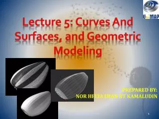
Lecture 5: Curves And Surfaces, and Geometric Modeling. PREPARED BY: NOR HELYA IMAN BT KAMALUDIN. INTRODUCTION ABOUT GEOMETRIC MODELING…. CAD tools have been defined as the melting pot of three disciplines: design , geometric modeling , and computer graphic .

E N D
Lecture 5: Curves And Surfaces, and Geometric Modeling PREPARED BY: NOR HELYA IMAN BT KAMALUDIN PTT105: Engineering Graphics
INTRODUCTION ABOUT GEOMETRIC MODELING… • CAD tools have been defined as the melting pot of three disciplines: design, geometricmodeling, and computer graphic. • A geometric model should be unique and complete to all engineering functions, from documentation to engineering analysis to manufacturing. PTT105: Engineering Graphics
CURVES • Geometric description of curves defining an object can be tackled in several ways. • A curve can be described by arrays of coordinate data or by an analytic equation. • Majority of the curves were circles, but some were free-form. • Those are curves arising from applications such as ship hull design to architecture. PTT105: Engineering Graphics
When they had to be drawn exactly, the most common tool was a set of templates known as French curves. • French curve: • carefully designed wooden curves • consist of pieces of conics and spirals. • A conic section is a curve obtained by intersecting a cone with a plane. • 3 types of conic section are ellipse,parabola,hyperbola. PTT105: Engineering Graphics
1. Ellipse • An ellipse is a smooth closed curve which is symmetric about its horizontal and vertical axes. • In geometry, an ellipse is results from the intersection of a cone by a plane in a way that produces a closed curve. • Circles are special cases of ellipses, obtained when the cutting plane is orthogonal to the cone's axis. • An ellipse is also the locus of all points of the plane whose distances to two fixed points add to the same constant. PTT105: Engineering Graphics
Example of an ellipse: PTT105: Engineering Graphics
2. Parabola • Parabola is a conic section, the intersection of a right circular conical surface and a plane parallel to a generating straight line of that surface. • For parabola, the locus of points are equidistant from a given point (the focus) and a corresponding line (the directrix) on the plane. • The parabola has many important applications such as in designing automobile headlight reflectors and ballistic missiles. PTT105: Engineering Graphics
Example of a parabola: PTT105: Engineering Graphics
3. Hyperbola • The hyperbola is one of the three kinds of conic section, formed by the intersection of a plane and a cone. • A hyperbola is an open curve with two branches, the intersection of a plane with both halves of a double cone. • The two pieces of branches formed mirror images of each other and resembling two infinite bows. PTT105: Engineering Graphics
Example of a hyperbola: PTT105: Engineering Graphics
SPLINES • Another mechanical tool of curve, called a splinewas also used. • Spline is a flexible strip of wood that are held in place and shape by metal weights, known as ducks. • A spline“tries" to bend as little as possible, resulting in shapes which are both aesthetically pleasing and physically optimal. PTT105: Engineering Graphics
Spline Curve • Description: Spline curve is one of the most fundamental parametric curve forms. It is a mathematical counterpart to a mechanical spline. • Features: • Curve that can minimize certain functionality • Act as piecewise polynomial (or rational polynomial) curves with certain smoothness properties. PTT105: Engineering Graphics
Example of Splines PTT105: Engineering Graphics
SURFACES • Surface models have an infinitely thin computer-calculated surface between their edges. • Although they appear to be solid, they are an empty shell. • The model on the left in the figure shows the previous object as a surface model. PTT105: Engineering Graphics
They appear to be a round hole through the model. • The hole is actually a tube simulating the surface of a hole, as can be seen in the center model, in which a surface panel has been removed. • Surface model often use wireframe models as a frame for their surfaces. PTT105: Engineering Graphics
Rectangular Surfaces • Rectangular surfaces are a map of a rectangular domain into 3D parametric surface. • Mapping the rectangular domain to a 2D parametric surface, resulting in a distortion of that rectangle. • For example, ifwe embed a curve in this domain rectangle, we will obtain a deformed curve. PTT105: Engineering Graphics
Application of rectangular surfaces PTT105: Engineering Graphics
SOLID GEOMETRIC MODELING • Solid models have both edge and surfaces, plus computer-calculated mass under their surfaces. • Solid models provides mass property information: volume, center of gravity, mass moment of inertia. • The example of solid model is shown below. PTT105: Engineering Graphics
It appears very similar to a surface model • But, if we sliced in in half, as demonstrated in the center model, it show truly solid. • Basic rule for solid modeling– all surfaces must touch another surface PTT105: Engineering Graphics
Example of Solid Modeling PTT105: Engineering Graphics
Solid Modeling • 3 different types of solid modeling: – Primitive modeling – Constructive solid geometry (CSG) – Feature-based modeling (FBM) PTT105: Engineering Graphics
1. Primitive Modeling • Objects described using basic geometrical forms. • Common geometric primitives. PTT105: Engineering Graphics
Example: PTT105: Engineering Graphics
2.Constructive Solid Geometry (CSG) • More flexible and powerful than primitive. • Allow Boolean Operations: - union, difference & intersection PTT105: Engineering Graphics
Boolean operation PTT105: Engineering Graphics
Example using CSG: PTT105: Engineering Graphics
Example using CSG: PTT105: Engineering Graphics
3. Feature-based Modelling (FBM) • 3D model is built using series of features, such as hole, slot, square block, etc. • Each feature can be independent or linked to other feature. • The geometry of each feature is controlled by modifiable constraints and dimensions. PTT105: Engineering Graphics
FBM: 3D operations • Basic concept – 2D cross-section or profile is produced – Depth is given to the profile • Generally 4 types** – Extrude – Revolve – Sweep – Blend **different terms might be used in different software/books PTT105: Engineering Graphics
1. 3D Ops: Extrude • A linear sweep, where the profile is given a depth in straight line, perpendicular to the profile plane PTT105: Engineering Graphics
2. 3D Ops: Revolve • The profile is rotated around a defined axis, 0 – 360 degree PTT105: Engineering Graphics
3. 3D Ops: Sweep • The new command and is similar to the EXTRUDE command, but it concentrates on using paths to define the direction of the extrusion. • This command SWEEP a 2D object along a path. PTT105: Engineering Graphics
3D Ops: Sweep & Blend PTT105: Engineering Graphics
Steps in building 3D object PTT105: Engineering Graphics
Examples of FBM + Boolean PTT105: Engineering Graphics