Exploring Finite Element Analysis: Methods, Applications & Tools
Understand the concept of FEA, different analysis types, steps involved, and professional software tools. Learn practical applications in engineering fields with advantages and numerical methods. Enhance your knowledge for solving real-world problems effectively.

Exploring Finite Element Analysis: Methods, Applications & Tools
E N D
Presentation Transcript
Introduction to Finite Element Analysis
Introduction to “Finite Element Analysis” What This Presentation Covers • Introduction to Different Numerical Method • Introduction to FEM - Concept & Philosophy • Practical Application of FEA • Need & Advantages of Finite Element Analysis • Different Professional FEA Tools/Software • Steps involved in any Finite Element Analysis – Best Practices Approach • Types of Analysis
Introduction to “Finite Element Analysis” Objective of this Session • By the End of this session, You will be able to : • Understand and apply the Concept of FEM / FEA on Actual practical day-to-day / complex problems • Understand Different Type of Analysis covered in FEA • Prepare a suitable FE model for a given problem • Know the Behavior of different type of FE Elements used , Concept of FE Mesh , Loads and Boundary Condition • Step by Step approach followed in any Finite Element Analysis
Introduction to “Finite Element Analysis” Introduction to FEA Methods to Solve Any Engineering Problem
Introduction to “Finite Element Analysis” Different Numerical Methods Finite Element Method (FEM) : Very Popular Method based upon discretization of component into Finite number of blocks (elements) Applications : Linear, Nonlinear, Thermal, Dynamics , Buckling and Fatigue Analysis Boundary Element Method (BEM) : It’s a very powerful and efficient technique to solve acoustics and NVH problems Just like Finite Element Method, it also requires Nodes and Elements but as the name suggest, it considers only the outer boundary of the domain Finite Volume Method (FVM) : All Computational Fluid Dynamics (CFD) soft wares are based upon FVM. Unit Volume is considered in Finite Volume Method (similar to Elements in Finite Element Method) Variable properties at nodes are Pressure , Velocity , Area , Mass etc. It is based on Navier – Stoke equations ( Mass ,Momentum and Energy Conservation equations) Finite Difference Method (FDM) : Finite Element and Finite Difference share many common things. In general, Finite difference Method is described as a way to solve difference equation. It uses Taylor’s series to convert differential equation into algebraic equation. Higher order terms neglected. Is it possible to use all the above listed methods (FEA ,BEM , FVM, FDM) to solve same problem (say Cantilever problem)? Answer : YES ! But the difference is in Accuracy achieved , programming ease and time required to obtain the solution
Introduction to “Finite Element Analysis” Are FEA and FEM different ? Finite Element Analysis (FEA) and Finite Element Method (FEM) both are one & the same. FEA is a method/process based upon FEM Term “FEA” is more popular in industries while “FEM” at Education centers
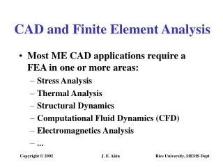
Introduction to “Finite Element Analysis” Why Finite Element Method ? FEA is the most widely applied computer simulation method in Engineering. It is very closely integrated with CAD/CAM applications. It is very well proven , tested and validated method for simulating any complex practical scenario in the area of Structural ,Thermal ,Vibration etc..
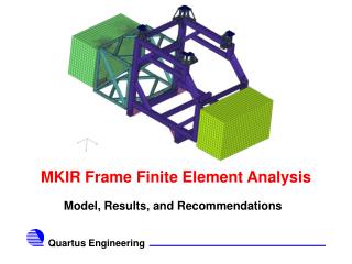
Introduction to “Finite Element Analysis” Application of FEM in Engineering • Mechanical / Aerospace / Civil Engineering / Automobile Engineering • Structural Analysis ( Static / Dynamic , Linear / Non-Linear ) • Thermal Analysis ( Steady State / Transient ) • Electromagnetic Analysis • Geomechanics • Biomechanics • etc….
Introduction to “Finite Element Analysis” Practical Applications of FEA • Aerospace Domain • Automotive Domain
Introduction to “Finite Element Analysis” Practical Applications of FEA • Hi-Tech /Electronics • Medical Devices
Introduction to “Finite Element Analysis” Practical Applications of FEA and many more ….
Introduction to “Finite Element Analysis” Advantages of FEA • Cost • Design Cycle time • No. of Prototypes • Testing • Design Optimization
Introduction to “Finite Element Analysis” Available Commercial FEA Tools/Software Packages
Introduction to “Finite Element Analysis” Analysis Types Structural Analysis Static Analysis Dynamic Analysis Modal Analysis Harmonic Analysis Non-Linear Linear Random Analysis
Introduction to “Finite Element Analysis” Steps involved in FEA • Understanding the Problem (Thermal , Structural, Dynamic etc) • Element Selection (Solid , Shell , Beams etc) • Deciding the Boundary Conditions (Constraints , Connections etc..) • Load Application (Point , Surface , Body loads etc..) Pre Processing • Solution(Solver , Sub step / Time step , Nonlinearity etc) Solution • In-Depth study & interpretation of Analysis Results (Sanity Checks) • Post processing of Results (Deflection , Stress , Strain etc..) • Report Preparation • Observation and Conclusion from the Analysis (MoS Calcs, Design ok) • Suggestion and Recommendation for Design Changes, if required. Post Processing
Introduction to “Finite Element Analysis” FEM Philosophy …in layman terms The Philosophy of FEA can be explained with a small example such as “ Measuring the Perimeter of a Circle” If one need to evaluate the perimeter of a circle without using the conventional formula (2*pi*r), FEA approach is analogous to Dividing the circle into a number of segments and joining the points using Straight lines Since it is very easy to measure the length of straight line. Measure the length of one line and multiply it by No. of lines to get the perimeter. Approximate results….isn’t it ? What if we want to achieve more accurate result?
Introduction to “Finite Element Analysis” Concept of Discretization (Meshing) Physical System FE Model
Introduction to “Finite Element Analysis” Concept of Discretization (Meshing) Concept of FEM is all about Discretization (Meshing) i.e. Dividing a big structure/component into small discrete Blocks (Nodes and Element concept) But why do we do this Meshing ??? No. of Points = 8 DoF per point = 6 Total No of Equations to be solved = 8 * 6 = 48 No. of Points = ∞ DoF per point = 6 Total No of Equations to be solved = ∞ * 6 = ∞ From Infinite to Finite…Hence the Term “Finite Element Method”
Introduction to “Finite Element Analysis” Concept of Discretization (Meshing)
Introduction to “Finite Element Analysis” Concept of Discretization (Meshing) • Parameters deciding the “Quality” of Mesh : • Aspect ratio • Skew / Warpage • Element internal Angles • and more… Bad Quality FEA Good Quality FEA Better the Mesh Quality , Better the Accuracy
Introduction to “Finite Element Analysis” Different Type of Elements Linear - 1st Order Element Quadratic 2nd Order Element Triangular Element 2D Quadrilateral Element 3D Hexahedral Element
Introduction to “Finite Element Analysis” Types of Contacts used in FEA Bonded Contact This is the default configuration and applies to all contact regions( surfaces, solids, faces, edges). If contact Regions are bonded, then no sliding or separation between faces or edges is allowed. This type of contact Allows for a linear solution since the contact length/area will not change during the application of the load. Eg: Welding, Glued connection, Bolted connection. No Separation Contact This contact setting is similar to the bonded case. It only applies to regions of faces(for 3D solids) or edges (for 2D plates). Separation of the geometries in this contact is not allowed, but small amount of frictionless Sliding can occur along contact geometries. Frictionless Contact This contact setting models standard unilateral contact, that is normal pressure equals to zero if separation occurs. Thus gaps can form in the model between bodies depending on the loading. This solution is non linear because the area of contact may change as the load is applied. A zero coefficient of friction is assumed, thus allowing free sliding. The model should be well constrained when using this contact setting. Frictional Contact In this contact setting, the two contacting geometries can carry shear stresses upto a certain magnitude across their interface before they start sliding relative to each other. This state is known as sticking. The model defines an equivalent shear stress at which sliding on the geometry begins as a fraction of contact pressure. Once the shear stress exceeded, the two geometries will slide relative to each other.
Introduction to “Finite Element Analysis” Types of Boundary Conditions, Loads & Results • Boundary Conditions : • Fixed Boundary Conditions (U , ROT etc.. = 0) • Prescribed Displacements (U , ROT , Temp etc.. ≠ 0) • Loads: • Point /Concentrated Load (Force) • Surface Load (Pressure , Flux etc..) • Body Load (Temp , Inertia g etc..) • Results: • Displacement • Reaction Forces • Stresses /Strains (Equivalent Von Mises , Directional & Principal ) • Temperature etc..
Introduction to “Finite Element Analysis” Finite Element Analysis – At a Glance Best Practice Approach
Plan your analysis Analysis type (Static/Dynamic, Linear/Non-Linear etc..) Material Details (isotropic/orthotropic , Constant/Temp dependent) Choice of Elements and Meshing (2D/3D , Hex / Tet) Results Evaluation (Detailed Post processing) Verification (Sanity Checks , Test data match) Introduction to “Finite Element Analysis” Best Practices Approach