X.25
X.25. Raj Jain Professor of CIS The Ohio State University Columbus, OH 43210 These slides are available at http://www.cse.ohio-state.edu/~jain/cis777-00/. Overview. X.25 Overview X.25 Protocol Layers X.25 Physical Layer X.25 Frame Level: LAPB X.25 Packet Level Call Setup/Disconnection.

X.25
E N D
Presentation Transcript
X.25 Raj Jain Professor of CIS The Ohio State UniversityColumbus, OH 43210 These slides are available at http://www.cse.ohio-state.edu/~jain/cis777-00/
Overview • X.25 Overview • X.25 Protocol Layers • X.25 Physical Layer • X.25 Frame Level: LAPB • X.25 Packet Level • Call Setup/Disconnection
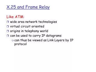
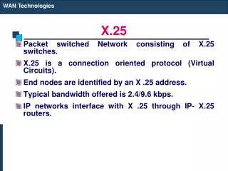
X.25 Overview • First packet switching interface. • Issued in 1976 and revised in 1980, 1984, 1988, and 1992. • Data Terminal Equipment (DTE) to Data Communication Equipment (DCE) interface User to network interface (UNI) • Used universally for interfacing to packet switched networks X.25 X.25 DTE DTE DCE DCE Your Computer
Virtual Circuits 24 B DCE DTE 2, 3 Network • Virtual Call • Two Types of Virtual Circuits: • Switched virtual circuit (SVC)Similar to phone call • Permanent virtual circuit (PVC)Similar to leased lines • Up to 4095 VCs on one X.25 interface A DTE DCE C DCE DTE 35
Packet Link Access Physical DCE X.25 Protocol Layers • X.21 often replaced by EIA-232 (RS-232C) • LAP-B = Link access procedure - Balanced • Packet layer = Connection-oriented transport over virtual circuits User Process User Process Packet LAP-B Link Access X.21 Physical DTE
Protocol Layers (Cont) • X.25 Packets • Data is broken into blocks • 3- or 4-byte packet header • Packets are broken into LAPB frames Data X.25 Level 3 Header LAP-B Header LAP-B Trailer
X.25 Physical Layer • Electrical and mechanical specifications of the interface • X.21 = 15-pin digital recommendation • X.21bis = X.21 twice = X.21 second Interim analog specification to allow existing equipment to be upgraded. Now more common than X.21 Þ X.21 Rev 2 • RS-232-C developed by Electronics Industries Association of America (EIA) is most commonUses 25-pin connector. Commonly used in PCs.
HDLC Family • Synchronous Data Link Control (SDLC): IBM • High-Level Data Link Control (HDLC): ISO • Link Access Procedure-Balanced (LAPB): X.25 • Link Access Procedure for the D channel (LAPD): ISDN • Link Access Procedure for modems (LAPM): V.42 • Link Access Procedure for half-duplex links (LAPX): Teletex • Point-to-Point Protocol (PPP): Internet • Logical Link Control (LLC): IEEE • Advanced Data Communications Control Procedures (ADCCP): ANSI • V.120 and Frame relay also use HDLC
HDLC • Primary station: Issue commands • Secondary Station:Issue responses • Combined Station: Both primary and secondary • Unbalanced Configuration: One or more secondary • Balanced Configuration: Two combined station • Normal Response Mode (NRM): Response from secondary • Asynchronous Balanced Mode (ABM): Combined Station • Asynchronous Response Mode (ARM): Secondary may respond before command
Flag Address Control Info FCS Flag Address 8b 8b 8 or 16b nb 16b 8b LAPB • Uses balanced mode subset of HDLC between DTE and DCE • Uses 01111110 as frame delimiterUses bit stuffing to avoid delimiters inside the frames • Uses HDLC frame format • Point-to-point: Only two stations - DTE (A), DCE (B)Addresses: A=00000011, B=00000001Address = Destination Addresses in Commands Source Address in Responses,
1 2 3 4 5 6 7 8 0 N(S) P/F N(R) 1 0 S P/F N(R) 1 1 M P/F M Control Field Format • N(S) = Send Sequence Number • N(R) = Receive Sequence Number = Expected next • P/F = Poll/Final = Command/Response • M = Set Async Balanced Mode (SABM), Disconnect, Unnumbered Ack, … • S = Supervisory function = Receiver Ready (RR), Receiver Not Ready (RNR), Reject (Rej) Information Supervisory Unnumbered
HDLC Frames • Information Frames: User data • Piggybacked Acks: Next frame expected • Poll/Final = Command/Response • Supervisory Frames: Flow and error control • Go back N and Selective Reject • Final No more data to send • Unnumbered Frames: Control • Mode setting commands and responses • Information transfer commands and responses • Recovery commands and responses • Miscellaneous commands and responses
Examples of HDLC Operation I,0,0 I,0,1 I,1,1 I,2,1 I,1,3 I,3,2 I,2,4 I,3,4 RR,4 I,3,0 RNR,4 RR,0,P RNR,4,F RR,0,P RR,4,F I,4,0 SABM Timeout SABM UA DISC UA (a) Line setup anddisconnect (b) Two-way dataexchange (c) Busy condition Fig 6.12 Stallings
Examples of Operation (Cont) I,3,0 I,4,0 I,5,0 Rej, 4 I,4,0 I,5,0 I,6,0 I,2,0 RR,3 I,3,0 RR,0,P RR,3,F I,3,0 RR,4 * * Timeout (d) Reject Recovery (e) Timeout Recovery Fig 6.12 Stallings
X.25 Packet Level • Packet Level = End-to-end • Packet level procedures: • Establishment and clearing of virtual calls • Management of PVCs • Flow Control • Recovery from error conditions
Call Setup/Disconnection Call Request Incoming Call Call Accepted Call Connected Data Data Data Data Clear Request Clear Indication Clear Confirmation Clear Confirmation
4b 4b General Format Identifier Logical Channel Group # Logical Channel Number Packet Type Identifier Packet Format • GFI = Type of packet.Bit 1: Qualifier. Q=1 Þ Higher level controlBit 2: 0ÞEnd-to-end confirm., 1ÞLocal conf. Bits 3,4: 01Þ 3-bit or 10 Þ7-bit sequence # • LCGN + LCN = 12-bit VC # w 4-bit Group • PTI = 20 possible packet types
Q D 1 0 Group # Channel # P(R) M P(S) 0 User Data Data w 7-bit Seq # Packet Format (Cont) • M = More segments • P(R) and P(S) refer to packet sequence #Different from N(R) and N(S) - frame sequence # Q D 0 1 Group # Channel # P(R) M P(S) 0 User Data Data w 3-bit Seq #
0 0 1 0 Group # Channel # Packet Type 1 Additional Info Control w 7-bit Seq # 0 0 1 0 Group # Channel # 0 Pkt Type 1 RR, RNR, and REJ packets with 7-bit seq # Packet Format (Contd) 0 0 0 1 Group # Channel # Packet Type 1 Additional Info Control w 3-bit Seq # 0 0 0 1 Group # Channel # P(R) Pkt Type 1 P(R) RR, RNR, and REJ packets with 3-bit seq #
Summary • X.21, LAPB • PVC and virtual call • VC numbers • M and D bits
Homework • Read Section 7.1 of McDyson and Spohn’s book • Submit answer to the following question: In X.25 why is the VC number used by one station is different from the VC number used by the other station? After all, it is the same full-duplex virtual circuit. • Due: Next week
Additional References • N. M. Thorpe and D. Ross, “X.25 Made Easy,” Prentice Hall, 1992, 192 pp. • W. Stallings, “Data and Computer Communications,” 5th Edition, Prentice Hall, 1996, Sections 6.4 and 9.4