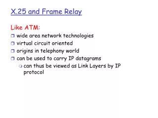
X.25 Protocol
X.25 Protocol. The X.25 Protocol. CCITT Recommendation X.25 First Published in 1976 Revisions Every 4 Years -- 1980, 1984, 1988 Interface Protocol for Packet Switched Networks Network Providers Intended to Be Telcos. The X.25 Protocol. The Model Network Has Multiple Nodes (DCEs)


X.25 Protocol
E N D
Presentation Transcript
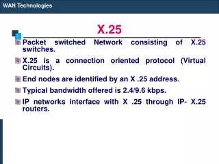
The X.25 Protocol CCITT Recommendation X.25 • First Published in 1976 • Revisions Every 4 Years -- 1980, 1984, 1988 • Interface Protocol for Packet Switched Networks • Network Providers Intended to Be Telcos
The X.25 Protocol The Model • Network Has Multiple Nodes (DCEs) • Host Computers (DTEs) Outside • Hosts Have Addresses Like Phone Numbers • Virtual Call Setup • Virtual Call Clear • Data Transfer DCE DTE X.25 Intra-Network Protocol DCE X.25 DCE DTE DCE X.25 DTE DCE
Flag LAPB Hdr Pkt Hdr Data CRC Flag Network X.25 Packet Level Link X.25 Frame Level (LAPB) Physical RS232, etc The X.25 Protocol The X.25 Protocol Layers Layer Name Description
The X.25 Protocol Physical Layer – Sort of • Flag Character (01111110) at Beginning and End • Data in between is LAPB Frame • Data Passed up to Frame Level • Data Transparency 011111010 011111 10 0 Frame Level (LAPB) Flag Data CRC Flag
The X.25 Protocol Frame Level – LAPB • Frame Level Header Has Frame Type • Sequence and Acknowledgement Numbers • Error Recovery Procedures • Endpoints Are DTE and Local DCE Packet Level LAPB Hdr Information Field
N(R) P/F N(S) 0 RR RNR REJ N(R) P/F 1 DISC SABM UA DM FRMR P/F 1 1 The X.25 Protocol LAPB Header Address Control • N(R) is Ack Nr and Counts Modulo 8 • N(S) is Seq Nr and Counts Modulo 8 • RR = Receiver Ready • RNR = Receiver Not Ready • REJ = Reject • SABM = Link Setup Req • UA = Unnumbered Ack • DM = Disconnected Mode • FRMR = Frame Reject Information Frame Supervisory Frames Unnumbered Frames
Local DTE Local DCE The X.25 Protocol LAPB Link Setup and Disconnect • SABM = Set Asynchronous Balanced Mode • UA Acknowledges SABM • DISC Requests Disconnect • UA Acknowledges DISC • Exchange on Local Link Only SABM UA Now in Data Transfer Mode DISC UA Now in Disconnected Mode
Local DTE Local DCE The X.25 Protocol LAPB Data Transfer • I-Frame Contains Packet • Seq from 0 - 7 and back to 0 • RR Gives Next Expected I-Frame • I-Frame Can also Acknowledge I-Frame #1 RR N(R)=2 I-Frame #2 RR N(R)=3 I-Frame #3 I-Frame #0 N(R)=4
The X.25 Protocol The X.25 Packet Level • Packet Header Has Packet Type • Channel Number Identifies Logical Connection • Sequence and Acknowledgement Numbers • No Error Recovery -- Data Can Be Lost • Addressing across Multi-Node Network Application Layer Pkt Hdr Data
Channel Nr Pkt Type P(R) P(S) 0 RR RNR P(R) 1 Call Req Call Acpt Clr Req Clr Conf Reset Req Reset Conf Intr Req Intr Conf Restart Req Restart Conf 1 1 The X.25 Protocol Packet Level Header Data Packet • Channel Nr Selects which Connection • P(R) is Ack Nr and Counts Modulo 8 • P(S) is Seq Nr and Counts Modulo 8 • RR = Receiver Ready • RNR = Receiver Not Ready Acknowledgement Packets Other Packets
Local DTE Local DCE Remote DCE Remote DTE The X.25 Protocol Call Setup Call Request • Each Channel is Distinct • Select Unused Channel • Different Channel Numbers on Each End • End to End is “Virtual Circuit” • VC = Local Chnl + Network Route + Remote Chnl • Internal Network Protocol Not Specified • Call Setup is End to End Locate Remote DCE Incoming Call Internal Protocol Call Accepted Call Connected
Local DTE Local DCE Remote DCE Remote DTE The X.25 Protocol Call Clearing Remote DCE from Call Setup Clear Request • Each Channel is Distinct • Channels Become Available • End to End is “Virtual Circuit” • Internal Network Protocol Not Specified • Clearing May be End to End or Local • Clear Packet Used to Report Procedure Errors Clear Indication Internal Protocol Clear Confirm Clear Confirm
Local DTE Local DCE Remote DCE Remote DTE The X.25 Protocol Data Transfer w/End to End Ack Remote DCE from Call Setup Data Packet #1 • Each Channel is Distinct • End to End is “Virtual Circuit” • Internal Network Protocol Not Specified • Each Data Pkt Has Seq Nr • Each RR Has Next Expected Seq Nr • Example Shows End to End Acknowledgement Data Packet #1 Internal Protocol RR P(R)=2 RR P(R)=2
Local DTE Local DCE Remote DCE Remote DTE The X.25 Protocol Data Transfer w/Local Ack Remote DCE from Call Setup Data Packet #1 • Each Channel is Distinct • End to End is “Virtual Circuit” • Internal Network Protocol Not Specified • Each Data Pkt Has Seq Nr • Each RR Has Next Expected Seq Nr • Example Shows Local Acknowledgement RR P(R)=2 Data Packet #1 Internal Protocol RR P(R)=2 Data Packet #2 Data Packet #2 RR P(R)=3 RR P(R)=3
Local DTE Local DTE Data Packet #1 RR P(R)=2 Data Packet #2 RR P(R)=3 The X.25 Protocol X.25 Without a Network • Two DTEs Communicating Directly • No Intervening Network • One DTE Plays the Role of DCE • LAPB Ensures Reliability • Acknowledgements “End to End” • DTE Addressing Immaterial
The X.25 Protocol End of Presentation