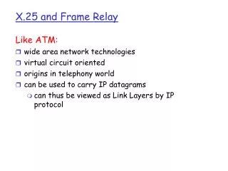
X.25 PROTOCOL
X.25 PROTOCOL. Presented by : EFA, Daniel Jr. G. VERGARA, Jonvon. X.25 Protocol. A packet-switched wide area network (WAN) developed in 1976 by the CCITT to provide a common interface protocol between public data networks. WAN Technology. Interface Protocol for Packet Switched Networks.


X.25 PROTOCOL
E N D
Presentation Transcript
X.25PROTOCOL Presented by: EFA, Daniel Jr. G. VERGARA, Jonvon
X.25 Protocol A packet-switched wide area network (WAN) developed in 1976 by the CCITT to provide a common interface protocol between public data networks. WAN Technology Interface Protocol for Packet Switched Networks
X.25 NETWORK PSE PSE DCE DTE DCE DTE DCE PSE PSE DCE DTE PAD DTE
X.25 X.25 Wide Area Network DTE DTE PAD DCE PSE DCE PAD Conceptual View of X.25
X.25 Network Devices X.25 network devices fall into three general categories: Data terminal equipment (DTE). Data circuit-terminating equipment (DCE). Packet switching exchange (PSE).
X.25 Network Devices • Data terminal equipment (DTE) • End systems that communicate with one another across the X.25 data network and include terminals, PCs, and network hosts • Data circuit-terminating equipment (DCE) • Communications devices such as modems and packet switches, that provide the interface between DTEs and PSE. • Packet switching exchanges (PSE) • Constitute the majority of the network • Transfers data from one DTE to another through the X.25 network
X.25 Network Devices • Packet Assembler/Disassembler (PAD) • PADs provide buffering (data storage), packet assembly and packet disassembly. • This operation includes adding an X.25 header.
PAD in Action X.25 Packet Terminal DTE Modem DCE Assembler/ Disassembler Buffer
7 Layers of OSI
X.25 Protocol Layers Layer 3 OSI Network Layer X.25 Packet Layer OSI Data-link Layer X.25 Frame Layer Layer 2 OSI Physical Layer X.25 Physical Layer Layer 1
X.25 Protocol Layers X.25 defines how packet mode terminals can be connected to a packet network. It also describes the procedures required to establish, maintain, and terminate a connection as well as a set of services that provide additional functions.
X.25 mapping to OSI Model Application Other Services Presentation Session Transport Network PLP X.25 Protocol Suite Data Link LAPB Physical x.21 bis, EIA/TIA-232, EIA/TIA-449, EIA-530, G.703
X.25 Physical Layer Protocol Called the X.21 digital interface. Designed to enable all-digital communications between DTEs and DCEs and to address the problems inherent in many of the preexisting EIA interface standards. It specifies how a DTE and DCE exchange signals to set up and clear calls.
X.25 Physical Layer • Several well-known standards are used for X.25 networks • X.21bis – supports up to 2 Mbps • 15-pin connector • RS-232 (EIA/TIA-232) – supports up to 19.2 Kbps • 25-pin connector • RS-449 (EIA/TIA-449) – supports up to 64 Kbps • 37-pin connector • V.35 – supports up to 2 Mbps • 34-pin connector • Uses serial communications in either asynchronous or synchronous modes
X.25 frame-layer protocol Layer 2 protocol intended to provide reliable data transfer between the DTE and DCE by transmitting data as a sequence of frames.
X.25 Frame Format CRC code A C D F F Flag Field 8 bits Address Field 8 bits Control Field 8 bits Data field (variable length In 8-bit groupings) Frame check Sequence (CRC-16) Flag Field 8 bits 01111110 7E hex 01111110 7E hex
Flag Address Control Data FCS Flag LAPB Frame Format Flag: (8 bits) Indicates start and end of frame (01111110) Address: (8 bits) DTE address is maintained in higher layer so this field is used to identify command and responses between DTE and DCE. A value of 0x01 indicates a command from DTE and responses from DCE while a value of 0x03 indicates commands from DCE and responses from DTE. Control: (8 bits) Contains sequence numbers, commands and responses for controlling data flow Data: (varies is size) Contains upper layer data FCS: (16 bits) Frame Check Sequence used to determine if an error has occurred in transmission (variation of CRC)
X.25 frame-layer protocol functions Transfer data efficiently and in a timely manner Synchronize the link, ensuring that the receive is synchronized to the transmitter Provide error detection and recovery Identify and report procedural errors to a higher layer for recovery
X.25 Packet Layer Protocol (PLP) A layer 3 protocol Creates network data units called packets that contain user information as well as control information. Responsible for establishing a connection, transferring data over the connection, and then terminating the connection. Responsible for creating virtual circuits and negotiating network services between a DTE and DCE.
PLP Operates in Five Modes • Call Setup • Used to setup virtual circuit for SVC • Data Transfer • Used for transferring data with both SVC and PVC • Idle • Used when SVC call has been established but no data is currently being transferred • Call Clearing • Used to end communication between DTEs for a SVC • Restarting • Used to synchronize DTE and DCE for all virtual circuits that exist between them