Camera Transformations in Computer Graphics: Projections and Viewing Techniques
This lecture delves into camera transformations within computer graphics, focusing on projection types including orthographic and perspective projections. Topics covered include the taxonomy of projections, the importance of direction of projection (DOP), and the matrix transformations necessary for rendering 3D scenes onto 2D screens. Additionally, the lecture details essential steps for creating a camera-centered view and utilizing OpenGL for implementing these transformations. It aims to enhance understanding for upcoming exams and practical applications in graphical programming.

Camera Transformations in Computer Graphics: Projections and Viewing Techniques
E N D
Presentation Transcript
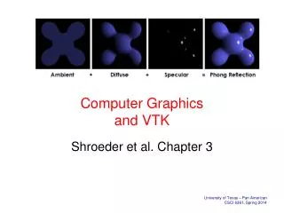
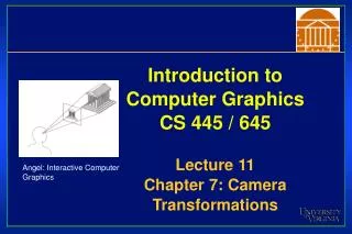
Introduction to Computer GraphicsCS 445 / 645Lecture 11Chapter 7: Camera Transformations Angel: Interactive ComputerGraphics
Announcements • Midterm is one week from today • Old tests will be available • Detailed list of chapter coverage made available • Homework on Thursday to sample coverage • Material covers up to today’s class
Taxonomy of Projections FVFHP Figure 6.10
Parallel Projection • Center of projection is at infinity • Direction of projection (DOP) same for all points View Plane DOP Angel Figure 5.4
Orthographic Projections • DOP perpendicular to view plane Front Angel Figure 5.5 Top Side
Oblique Projections • DOP not perpendicular to view plane Cavalier (DOP = 45o) tan(a) = 1 Cabinet (DOP = 63.4o) tan(a) = 2 H&B
Oblique Parallel-Projection Oblique View Volume Transformed View Volume
Oblique Parallel-Projection Oblique View Volume Transformed View Volume
Transformation Matrix Vp HB Matrix 7-13
Orthographic Projection • Simple OrthographicTransformation • Original world units are preserved • Pixel units are preferred
Orthographic: Screen Space Transformation left =10 m right = 20 m top=20 m (max pixx, max pixy) (height in pixels) (0, 0) bottom=10 m (width in pixels)
Orthographic: Screen Space Transformation (Normalization) HB Matrix: 7-7 • left, right, top, bottom refer to the viewing frustum in modeling coordinates • width and height are in pixel units • This matrix scales and translates to accomplish the transition in units
Perspective Transformation • First discovered by Donatello, Brunelleschi, and DaVinci during Renaissance • Objects closer to viewer look larger • Parallel lines appear to converge to single point
3-Point Perspective 2-Point Perspective 1-Point Perspective Perspective Projection • How many vanishing points? Angel Figure 5.10
Perspective Projection • In the real world, objects exhibit perspective foreshortening: distant objects appear smaller • The basic situation:
How tall shouldthis bunny be? Perspective Projection • When we do 3-D graphics, we think of the screen as a 2-D window onto the 3-D world:
Viewplane X P (x, y, z) x’ = ? (0,0,0) Z Perspective Projection • The geometry of the situation is that of similar triangles. View from above: • What is x’ ? d
Perspective Projection • Desired result for a point [x, y, z, 1]T projected onto the view plane: • What could a matrix look like to do this?
A Perspective Projection Matrix • Answer:
A Perspective Projection Matrix • Example: • Or, in 3-D coordinates:
Projection Matrices • Now that we can express perspective foreshortening as a matrix, we can compose it onto our other matrices with the usual matrix multiplication • End result: a single matrix encapsulating modeling, viewing, and projection transforms
Perspective vs. Parallel • Perspective projection • Size varies inversely with distance - looks realistic • Distance and angles are not (in general) preserved • Parallel lines do not (in general) remain parallel • Parallel projection • Good for exact measurements • Parallel lines remain parallel • Angles are not (in general) preserved • Less realistic looking
Classical Projections Angel Figure 5.3
Viewing in OpenGL • OpenGL has multiple matrix stacks - transformation functions right-multiply the top of the stack • Two most important stacks: GL_MODELVIEW and GL_PROJECTION • Points get multiplied by the modelview matrix first, and then the projection matrix • GL_MODELVIEW: Object->Camera • GL_PROJECTION: Camera->Screen • glViewport(0,0,w,h): Screen->Device
OpenGL Example void SetUpViewing(){ // The viewport isn’t a matrix, it’s just state... glViewport( 0, 0, window_width, window_height ); // Set up camera->screen transformation first glMatrixMode( GL_PROJECTION ); glLoadIdentity(); gluPerspective( 60, 1, 1, 1000 ); // fov, aspect, near, far // Set up the model->camera transformation glMatrixMode( GL_MODELVIEW ); gluLookAt( 3, 3, 2, // eye point 0, 0, 0, // look at point 0, 0, 1 ); // up vector glRotatef( theta, 0, 0, 1 ); // rotate the model glScalef( zoom, zoom, zoom ); // scale the model }
A 3D Scene • Notice the presence ofthe camera, theprojection plane, and the worldcoordinate axes • Viewing transformations define how to acquire the image on the projection plane
Viewing Transformations • Create a camera-centered view • Camera is at origin • Camera is looking along negative z-axis • Camera’s ‘up’ is aligned with y-axis
2 Basic Steps • Align the two coordinate frames by rotation
2 Basic Steps • Translate to align origins
Creating Camera Coordinate Space • Specify a point where the camera is located in world space, the eye point • Specify a point in world space that we wish to become the center of view, the lookat point • Specify a vector in worldspace that we wish to point up in camera image, the up vector • Intuitive camera movement
Constructing Viewing Transformation, V • Create a vector from eye-point to lookat-point • Normalize the vector • Desired rotation matrix should map this vector to [0, 0, -1]T Why?
Constructing Viewing Transformation, V • Construct another important vector from the cross product of the lookat-vector and the vup-vector • This vector, when normalized, should align with [1, 0, 0]TWhy?
Constructing Viewing Transformation, V • One more vector to define… • This vector, when normalized, should align with [0, 1, 0]T • Now let’s compose the results
Compositing Vectors to Form V • We know the three world axis vectors (x, y, z) • We know the three camera axis vectors (r, u, l) • Viewing transformation, V, must convert from world to camera coordinate systems
Compositing Vectors to Form V • Remember • Each camera axis vector is unit length. • Each camera axis vector is perpendicular to others • Camera matrix is orthogonal and normalized • Orthonormal • Therefore, M-1 = MT
Compositing Vectors to Form V • Therefore, rotation component of viewing transformation is just transpose of computed vectors
Compositing Vectors to Form V • Translation component too • Multiply it through
Final Viewing Transformation, V • To transform vertices, use this matrix: • And you get this: