Download
1 / 31
330 likes | 521 Vues
The DEPFET Active Pixel Sensor as Vertex Detector for the ILC. Vertex Detector at ILC DEPFET Principle Performance Radiation Hardness Matrix Operation Support ASICs Testbeam Results Module Concept Power Consumption Conclusions. DEPFET collaboration: Bonn, Mannheim, MPI, Aachen, Prague.

E N D
The DEPFET Active Pixel Sensor as Vertex Detector for the ILC • Vertex Detector at ILC • DEPFET Principle • Performance • Radiation Hardness • Matrix Operation • Support ASICs • Testbeam Results • Module Concept • Power Consumption • Conclusions DEPFET collaboration: Bonn, Mannheim, MPI, Aachen, Prague
The Linear Collider Project • 200 GeV < √s < 500 GeV (possibility of upgrade to 1 TeV) • Integrated luminosity ~ 500 fb-1 in 4 years • Start in 2015 ? • Needs an excellent vertex detector: b- and c- tacking, Vertex charge reconstruction • Impact parameter resolution: 5 mm +2 10 mm/(p sin2/3Q) (p in GeV/c) • needs small pixels (~25 x 25 mm2) • minimal scattering material: ~0.1% X0/layer (= 100 mm silicon!)
Linear Collider Vertex Detector Background (Beamstrahlung): 140,000 e+e- pairs/BX 0.03 hits/mm2/BX (at R=15mm, B=4T) Bunch train: (x 2820) => 85 hits/mm2/BT => 10% occupancy for 25 mm2 pixel Need ~ 20 readout cycles/BT to keep occupancy low Need ~ 50 MHz line rate for pixel matrix readout Radiation: 100krad in 5 years (at 15 mm radius, 4T) ILC time structure: 2820 bunches spaced by 337 ns 199 ms between trains (1/200 duty cycle)
Three Detector Concepts SiD -: small radius, high B field -: few track meas. points with high res. (Si) -: Si-W Calorimetry -: VTX: rmin=1.4 cm LDC -: med. radius, med. B field -: many track meas. points with med. res. (TPC) -: Si-W Calorimetry -: VTX: rmin=1.5 cm GLD -: large radius, low B field -: many track meas. points with med. res. (TPC) -: Sci.-W Calorimetry -: VTX: rmin=1.7 cm
Pixel Vertex Detector at the ILC • pixel size: 20-30 µm • low mass: 0.1 %Xo per layer • close to IP, r = 15 mm (1st layer) (26, 37, 48, 59 mm) • 20 ns/row read out time • 5 barrels – stand alone tracking LDC TESLA TDR Design 1st layer module: 100x13 mm2, 2nd-5thlayer : 125x22 mm2 ∑120 modules Several Sensor Concepts: CCDs, MAPs, SOI, DEPFETs
source top gate drain clear bulk + - - - - - - - + n+ p+ p+ n+ n+ - p + + n internal gate - - n p+ The DEPFET active pixel sensor • Charge generated in fully depleted bulk • Fast charge collection by drift underneath the transistor channel • Modulates the transistor current (400 pA/e for ILC layout) • Combined function of sensor and amplifier • Low capacitance and low noise (10-20 fC) • Signal charge remains undisturbed by readout • Internal storage • Complete clearing of signal charge • No reset noise Depleted Field EffectTransistor
Matrix operation • Charge collection in "OFF" state of the transistor • Select one row via external gates and measure pedestal + signal current • Reset that row and measure pedestal currents ….. • Only one single row active at a time and dissipating power • However, sensor is sensitive even if DEPFET is OFF!
PXD4 - DEPFET: Two projects on one wafer Metal 2 Metal 1 Poly 2 Poly 1 Double metal, double poly process
Lab Measurements Low intrinsic noise demonstrated by spectroscopic measurements with single pixels: 2.2 el rms noise (at room temperature, 6 ms shaping time)
Clear (Reset) • DEPFET Matrix Mode • Accumulate • Read (1) • Clear • Read (2) • Accumulate • Signal = Read(1) – Read(2) • (Correlated sampling, pedestal suppression) • Clear efficiency important: • Depends on: • Clear contact voltage • Clear gate voltage • Incomplete clear reduces signal and adds noise • Complete clear in wide parameter range • Clearing time < 10ns achieved
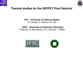
Radiation Hardness Bulk damage: mainly by neutrons from calorimeters -> negligible Oxide damage due to charged particles: 100 kRad in 5 years at 15mm 1. positive oxide charge and positively charged oxide traps have to be compensated by a more negative gate voltage: negative shift of the theshold voltage 2. increased density of interface traps: higher 1/f noise and reduced mobility (gm) Gate Dielectrics 180 nm SiO2 + 30 nm Si3N4
"ON" "OFF" 3.5h 123.5h 293.5h annealing Radiation Hardness 55Fe Irradiations on DEPFET teststructures a) Irradiation in off state (gate voltage off) b) Irradiation in on state (gate voltage on) Column readout of matrix: T(ON)/T(OFF) ~ 1/1000 ! Irradiated: 913 kRad Noise: 7.9 e at 23 C 6 ms shaping time Threshold shift reasonably small ~4 V, gate voltage up to 20V -> can be compensated No change of gq (amplification) Saturation for > 100 kRad -> No problems for operation at ILC -∆Vth (V) kRad
DEPFET Matrix Test System Switcher I: selects rows for readout (switch external gate) Switcher II: clears rows Curo II readout chip 128 channel current amplifier for column readout Internal pipeline & 0-suppression DEPFET matrix 64x128 pixels 28.5x36 mm2
4.6 mm 4.8 mm Support ASICs: Switcher • 64 channels with 2 analog MUX outputs (‘A’ and ‘B’) • can switch up to 25 V • digital control ground + supply floating • fast internal sequencer for programmable pattern(operates up to 80MHz) • present dissipation: 1mW/channel @ 30MHz • 0.8µm AMS HV technology Switcher: provides gate and clear signals 20V ! 2x64 outputs with spare pads
Support ASICs: Curo CURO: 128 channel readout chip • On-chip pedestal subtraction (correlated double sampling) • Real time hit finding and zero suppression • Hit addresses store in on-chip RAM • 0.25µm CMOS technology • Row rate of 25 MHz has been achieved
1 2 3 4 Scintillator DEPFET Scintillator 3 x 3 mm² beam Testbeam DESY test beam with 6 GeV e- Bonn ATLAS telescope system: • double sided strip detectors, 300μm • pitch 50 μm (no intermediate strips) • DEPFET: • 128x64 (28.5x36 µm2) • 450 μm thick • frame time 1.8 ms (limited by DAQ) • sample-clear-sample: 1 μs
Clustering Look for clusters: Seed cut >5σ Neighbour cut >2σ Typical cluster size: 5-6 pixels Combine signals seed & neighbours Signal: 32500 e Full 128 x 64 matrix Noise: 258 e Noise dominated by pickup: Front end: 160 e S/N (3x3) = 126 (scaled to 50 mm detector: 14)
Position Resolution Hit positions reconstructed using the CoG algorithm Note: pixelsize X=36µm Y=28.5µm Terrible, but … due to multiple scattering select "stiff tracks" using 2 cut Price: lose statistics
r=15.5 mm Module Concept & Material Budget Cross Section • Innermost Layer: • One self supporting Si-sensor • Readout at both ends • Sensitive area thinned to 50 mm • Support frame not thinned (300 mm) • Thinned (50 mm) ASIC bump bonded
Processing thin detectors (50 mm) a) oxidation and back side implant of top wafer c) process passivation Top Wafer open backside passivation b) wafer bonding and grinding/polishing of top wafer d) deep etching opens "windows" in handle wafer Successfully tested with MOS diodes (keep low leakage current ~ 800 pA/cm2)
Material Budget Estimated Material Budget (1st layer): Pixel area: 100x13 mm2, 50 μm: 0.05% X0 steer. chips: 100x2 mm2, 50 μm: 0.008% X0 (perforated) frame :100x4 mm2, 300 μm: 0.05% X0 _ Total material/ sensitive layer: 0.11%X0
Module Concept/Power Consumption DEPFET Matrix: power per active pixel: 50 mW only one row active: 0.5-0.8 W/row duty cycle: 1/200 5 layer detector: 0.5 W Switcher: power per active row: 6.3 mW duty cycle: 1/200 5 layer detector 4 mW CURO: power/channel (50MHz) 2.8 mW duty cycle: 1/200 5 layer detector: 2.6 W Total: 3.1 W Only 0.5 W in active area (no cooling of sensors needed) Only 2.6 W at the end flanges Low power consumption further reduces material needs
Project Status - in Summary • thinning technology • steering chips Switcher II • double metal/double poly technology • r/o chips Curo II • tolerance against ion. radition • beam test
Conclusions • DEPFET technology established (double metal/double poly) • Low intrinsic noise and complete clear demonstrated • Thinning technology established • Radiation tolerance up to 1 Mrad demonstrated • Readout and control ASICs developed and produced • Successful operation in beam test • Advantages for ILC Operation: • Signal generation and collection in depleted bulk • large and fast signal • First amplification step integrated • low noise • RAM addressing of pixels (no charge transfer) • fast readout, radiation tolerant • Power dissipation only during readout cycle • low power • Wafer scale arrays (6”) possible • simple modules, less material • Inhouse development & fabrication • complete control of design & technology
Workshop A Vertex Detector for the ILC - Physics and Technologies - May 28, 2006 - May 31, 2006 http://www.hll.mpg.de/~lca/ringberg
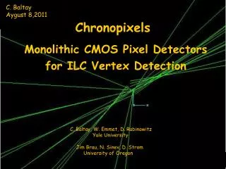
The competitors.... See https://wiki.lepp.cornell.edu/wws/bin/view/Projects/VtxProjects charge coll. in epi. layer CMOS MAPS in various "flavours" CP-CCD ISIS SOI Sensors DEPFET charge coll. in fully depl. bulk
Alternatives/Competitors Hybrid Pixels: Pixel detector with bump-bonded electronics (e.g. ATLAS/CMS pixels): problems: power and material! CCDs: used very successfully in SLD problems: power, speed => continuous shifting => time distance relation => radiation hardness (transfer efficiency) promising concept: internal storage pixels (ISIS) MAPS: Monolithic Active Pixel Senors: intergrated CMOS electronics uses “standard” CMOS: complex signal processing possible (0- suppression, pipeline) problems: speed, cross-talk, power CMOS process: small, slow and diffusing signal from thin (~15 mm) partially depleted epi-layer Small sensor chips (yield problem), recticles epi CCD epi MAPS
Alternatives/Competitors: MAPS N-well used for signal collection Only p-well possible for processing N- & p-well only in periphery Successful prototypes S/N: 20/1 Resolution < 2 mm However: signal distributed over many pixels Speed: not yet to LHC specs (inner layer) Power: ?????
Alternatives/Competitors: CCD CCDs with double column parallel reaout 25 MHz with 1.9 V !!! Noise: 60 e- Radiation damage? Wafer scale devices? New concept: ISIS CCDs In situ storage of ~ 20 “events” Exists for high speed optical cameras Immune to noise pickup from beam (SLD lession) Why whisper just when an express train roars through the station? (Chris Demerell)
An (un)biased comparisson.... No clear concept for the ILC. Feasibility shown, looking for industrial partners to continue.
The XEUS mission (2015) • Mission concept: • X-ray telescope consisting of two satelites, mirror (MSC) and detector (DSC) spacecraft • Formation flight; active control of focal length with 1 mm3 accuracy • Replacement of DSC possible • Increase of mirror surface from 6 m2 to 30 m2 possible • Total mission lifetime ca. 25 yrs. • 2 mirror technologies in discussion: Slumped glass / ESA high precision pore optics