Download

1 / 6
60 likes | 74 Vues
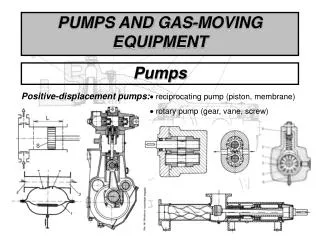
A centrifugal pump is a continuously acting pump that moves liquid by accelerating it radially outward in a rotating member (called an impeller) to a surrounding case. The impeller is essentially a rotating disk with vanes attached to it. Arrows indicate the direction of rotation and the direction of flow. The vanes on the impeller are curved backward, since this shape provides the most stable flow characteristics. This type of pump is by far the most common in use in buildings because of its simple construction and relatively low cost.<br>This paper describes the different types of centrifugal pumps, how they are constructed, and their performance and efficiency characteristics, applications in buildings, installation, and maintenance.<br>Pump Types and Nomenclature<br>The types of centrifugal pumps used in buildings are often confusing because such pumps are identified in a number of different ways, according to (a) the internal design, (b) single-suction versus double-suction configuration, (c) the shape of the impeller and its operating characteristics, (d) the casing design, (e) the type of connection between the motor and pump, (f) the position of the pump in relation to the water being pumped, and (g) the number of stages of the pump.<br>Internal design: The casing of a pump is the housing that encloses the impeller and collects the liquid being pumped. The liquid enters at the eye, located at the center of the impeller. It is the impeller that imparts energy to the liquid. After being rotated by the vanes on the impeller, the liquid is discharged with a greatly increased velocity at the periphery, where it is guided to the discharge nozzle through a spiral-shaped passage called a volute. This shape is designed to result in an equal flow velocity at all points around the circumference.<br>Single-suction versus double-suction configuration: The single-suction pump has a spiral-shaped casing and is most commonly used. The water enters the impeller from only one side. In the double-suction pump, the water enters both sides of the double-suction impeller so that hydraulic unbalance is practically eliminated. Since only half the flow enters each side of the impeller, problems with inlet design of higher-flow pumps are somewhat relieved. The impeller is usually mounted between two bearings, and the casing is split axially to permit convenient servicing of the pump.<br>Shape of the impeller: Impellers are curved to minimize the shock losses of flow in the liquid as it moves from the eye to the shrouds, which are disks that enclose the impeller vanes. If an impeller has no shrouds it is called an open impeller. This type usually is used where the water being pumped contains suspended solids. If an impeller has two shrouds, it is called a closed impeller; it requires little maintenance and usually retains its operating efficiency longer than open impellers. If the impeller has one shroud, it is called a semi open impeller.<br>Casing design: Casing is typed as radially split or axially split. The axially split casing is one that is split parallel to the shaft axis so that the pump maybe opened without disturbing the system piping, which makes it convenient to service. Radially split casings are split perpendicular to the shaft axis, resulting in a simpler joint design.<br>Type of connection between motor and pump: A separately coupled pump is one in which the electric motor drive is connected to the pump by means of a flexible coupling. Both pump and motor are mounted on a structural baseplate to provide support and maintain shaft alignment. A close coupled pump is one in which the same shaft is used for both the motor and pump. This construction results in low initial cost and installation cost and avoids alignment problems. It may also result in motor noise being transmitted to the pump and piping. A motor-face-mounted pump is one in which the pump is separately coupled with a face-mounted motor. This arrangement substitutes a structural connection between the pump and motor. It eliminates the need for a structural baseplate and minimizes coupling alignment problems.<br>Support of the pump: Horizontal dry-pit support is one where the pump is located with the shaft in a horizontal position in a dry location such as a basement floor or even a special pit constructed for the pump. The pump assembly is supported by the floor, and the structural baseplate is usually grouted to the floor. This is the most common support arrangement. In-line pumps are supported directly by the system piping; i.e., the piping carries the weight of the pump. The pump-motor assembly is usually mounted vertically in order to save floor space and center the weight over the piping. Some smaller pumps may hang horizontally from the piping, and some larger vertically mounted pumps may also rest on the floor. Wet-pit pumps are those which are immersed in the liquid to be pumped. This is most common with sump pumps where the pumping end is immersed in the liquid in the sump. The pump may be supported on the floor of the sump, or it may be suspended from a structural floor above the sump.<br>Bearing support: Shaft support is usually provided by ball bearings which are lubricated by grease or oil. Some types of pumps, such as submersible pumps (described below), depend on the liquid being pumped to lubricate the bearings. In such pumps, sleeve or journal bearings are used. A between-bearing pump is a centrifugal pump whose impeller is supported by bearings on each side. This design is usually built with a double-suction impeller and with the casing split in the axial direction so that the top can be lifted off and the rotating element removed. An overhung impeller pump is a centrifugal pump that has the impeller mounted on the end of a shaft that over-hangs its bearings. In-line circulating pumps are of this type.<br>Single-stage versus multistage pumps: A single-stage pump is one which has only one impeller. The total head is developed by the pump in one stage. A multistage pump is one which has two or more impellers. The total head is developed in multiple stages. Vertical turbine pumps are a unique type of multistage pump. They are designed primarily to pump water from deep wells and are long and slender.<br>Centrifugal Pump Construction<br>Materials: Centrifugal pumps used for most building services are built with cast-iron casings, bronze impellers, and bronze small parts. Stainless-steel impellers and stainless-steel small parts also are common. Cast-iron impellers may be used, but the life of a cast-iron impeller is shorter than that of a bronze or stainless-steel impeller.<br>Shafts, seals, and bearings: The shaft used to drive the impeller of the pump enters the casing through an opening that must be sealed to prevent leakage around the shaft (i.e., the seal must prevent liquid from leaving and air from entering). Two types of seals are used: soft fiber packing and mechanical face seals. Where packing is used, the shaft enters the opening through a stuffing box. Liquid is prevented from leaking out by filling this opening with a soft fiber packing. The packing material, which is relatively inexpensive, can usually be replaced without disassembling the pump. However, the packing will leak about 60 drops per minute and requires periodic adjustment. Mechanical seals are commonly used instead of packing because they are reliable, have good life expectancy, are practically leak-free, and do not require periodic adjustment.<br>Pump Characteristics<br>Capacity: The capacity of a pump is the rate of flow of liquid through the impeller expressed in gallons per minute (gpm) or cubic meters per hour (m3/h).<br>Total head: Head h is the energy per unit weight of a fluid due to (a) its pressure head hp, (b) its velocity head hv, and (c) its elevation head Z above some datum. It is commonly expressed as the height of a column of water in feet (or meters) which is necessary to develop a specific pressure. The total head developed by a pump is equal to the discharge head hd minus the suction head hs. The discharge head is the energy per unit weight of fluid on the discharge side of the pump. The suction head is the energy per unit weight on the suction side of the pump.<br>The static head Z is the static elevation measured in feet (meters) at the same point where the pressure is measured. Note that if a pressure gage is used, the center of the gage is the measurement point for the static head. The centerline of the pump impeller is usually used as the reference point for such measurements. The symbols and units used in this section are the same as those used by the Hydraulic Institute.<br>Efficiency: The efficiency in percent with which the pump operates is the ratio of the output power to the input power multiplied by 100. Efficiency varies with capacity reaching a maximum value at one capacity where the sum of all losses is a minimum.<br>Net positive suction head: Net positive suction head (NPSH) is the total suction head in feet (meters) of liquid in absolute pressure terms determined at the pump impeller, minus the vapor pressure of the liquid in feet (meters). The net positive suction head required (NPSHR) by the pump is determined by test and is the NPSH value at which the pump total head has decreased by 3% because of low suction head and resulting cavitation within the pump. In multistage pumps, the 3% head reduction refers to the first stage head and the NPSHR increases with capacity.<br>Speed: Usually a centrifugal pump is driven by a constant-speed electric motor. However, it is more efficient to control a pump by a variable-speed drive. The extra cost of variable-speed drives can be justified by the resultant savings in electric power.<br>System head curve: In order to move liquid through any system of pipes, the pump must produce a total head equal to or greater than the total head required by the system. The system head usually increases with flow rate, and if plotted versus capacity, it is called the system head curve. The shape of the system head curve is an important consideration in the proper selection of a pump in building services. The total head required to pump liquid through a system is the sum of the static head and the head due to friction loss in the system. For example, to pump water to the top of a 50-ft (15-m) building, the total head required is 50 ft (15 m) plus some friction loss. If the friction loss at the required flow is equivalent to a head of 10 ft (3 m), the total head required is 60 ft (18 m). When the flow is zero, there is no friction loss so the total head required is only 50 ft (15 m). The pump will operate where the pump curve intersects with the system head curve; at this point the full flow required will be pumped.<br>Because the pump is subject to wear, the total head output is reduced. As a result, there is a reduction in flow. However, note that the reduction is greater when there is a high static head than when the head is due only to friction losses. Hence, it is important that the system head curve and pump characteristic curve be compared at the time of pump selection to ensure that a 10% reduction in pump output, due to wear, does not result in a significant reduction in flow rate.<br>Pump efficiency: Centrifugal pumps are more efficient at high flow rates and moderate heads than at low flow rates and high heads.<br><br>Source: https://dticorp.com/improving-lives-with-water-pumps-and-equipment/ <br>

E N D
A centrifugal pump is a continuously acting pump that moves liquid by accelerating it radially outward in a rotating member (called an impeller) to a surrounding case. The impeller is essentially a rotating disk with vanes attached to it. Arrows indicate the direction of rotation and the direction of flow. The vanes on the impeller are curved backward, since this shape provides the most stable flow characteristics. This type of pump is by far the most common in use in buildings because of its simple construction and relatively low cost. This paper describes the different types of centrifugal pumps, how they are constructed, and their performance and efficiency characteristics, applications in buildings, installation, and maintenance. Pump Types and Nomenclature The types of centrifugal pumps used in buildings are often confusing because such pumps are identified in a number of different ways, according to (a) the internal design, (b) single-suction versus double- suction configuration, (c) the shape of the impeller and its operating characteristics, (d) the casing design, (e) the type of connection between the motor and pump, (f) the position of the pump in relation to the water being pumped, and (g) the number of stages of the pump. Internal design: The casing of a pump is the housing that encloses the impeller and collects the liquid being pumped. The liquid enters at the
eye, located at the center of the impeller. It is the impeller that imparts energy to the liquid. After being rotated by the vanes on the impeller, the liquid is discharged with a greatly increased velocity at the periphery, where it is guided to the discharge nozzle through a spiral-shaped passage called a volute. This shape is designed to result in an equal flow velocity at all points around the circumference. Single-suction versus double-suction configuration: The single- suction pump has a spiral-shaped casing and is most commonly used. The water enters the impeller from only one side. In the double-suction pump, the water enters both sides of the double-suction impeller so that hydraulic unbalance is practically eliminated. Since only half the flow enters each side of the impeller, problems with inlet design of higher- flow pumps are somewhat relieved. The impeller is usually mounted between two bearings, and the casing is split axially to permit convenient servicing of the pump. Shape of the impeller: Impellers are curved to minimize the shock losses of flow in the liquid as it moves from the eye to the shrouds, which are disks that enclose the impeller vanes. If an impeller has no shrouds it is called an open impeller. This type usually is used where the water being pumped contains suspended solids. If an impeller has two shrouds, it is called a closed impeller; it requires little maintenance and usually retains its operating efficiency longer than open impellers. If the impeller has one shroud, it is called a semi open impeller. Casing design: Casing is typed as radially split or axially split. The axially split casing is one that is split parallel to the shaft axis so that the pump maybe opened without disturbing the system piping, which makes it convenient to service. Radially split casings are split perpendicular to the shaft axis, resulting in a simpler joint design. Type of connection between motor and pump: A separately coupled pump is one in which the electric motor drive is connected to the pump by means of a flexible coupling. Both pump and motor are mounted on a structural baseplate to provide support and maintain shaft alignment. A
close coupled pump is one in which the same shaft is used for both the motor and pump. This construction results in low initial cost and installation cost and avoids alignment problems. It may also result in motor noise being transmitted to the pump and piping. A motor-face- mounted pump is one in which the pump is separately coupled with a face-mounted motor. This arrangement substitutes a structural connection between the pump and motor. It eliminates the need for a structural baseplate and minimizes coupling alignment problems. Support of the pump: Horizontal dry-pit support is one where the pump is located with the shaft in a horizontal position in a dry location such as a basement floor or even a special pit constructed for the pump. The pump assembly is supported by the floor, and the structural baseplate is usually grouted to the floor. This is the most common support arrangement. In-line pumps are supported directly by the system piping; i.e., the piping carries the weight of the pump. The pump-motor assembly is usually mounted vertically in order to save floor space and center the weight over the piping. Some smaller pumps may hang horizontally from the piping, and some larger vertically mounted pumps may also rest on the floor. Wet-pit pumps are those which are immersed in the liquid to be pumped. This is most common with sump pumps where the pumping end is immersed in the liquid in the sump. The pump may be supported on the floor of the sump, or it may be suspended from a structural floor above the sump. Bearing support: Shaft support is usually provided by ball bearings which are lubricated by grease or oil. Some types of pumps, such as submersible pumps (described below), depend on the liquid being pumped to lubricate the bearings. In such pumps, sleeve or journal bearings are used. A between-bearing pump is a centrifugal pump whose impeller is supported by bearings on each side. This design is usually built with a double-suction impeller and with the casing split in the axial direction so that the top can be lifted off and the rotating element removed. An overhung impeller pump is a centrifugal pump that has the
impeller mounted on the end of a shaft that over-hangs its bearings. In- line circulating pumps are of this type. Single-stage versus multistage pumps: A single-stage pump is one which has only one impeller. The total head is developed by the pump in one stage. A multistage pump is one which has two or more impellers. The total head is developed in multiple stages. Vertical turbine pumps are a unique type of multistage pump. They are designed primarily to pump water from deep wells and are long and slender. Centrifugal Pump Construction Materials: Centrifugal pumps used for most building services are built with cast-iron casings, bronze impellers, and bronze small parts. Stainless-steel impellers and stainless-steel small parts also are common. Cast-iron impellers may be used, but the life of a cast-iron impeller is shorter than that of a bronze or stainless-steel impeller. Shafts, seals, and bearings: The shaft used to drive the impeller of the pump enters the casing through an opening that must be sealed to prevent leakage around the shaft (i.e., the seal must prevent liquid from leaving and air from entering). Two types of seals are used: soft fiber packing and mechanical face seals. Where packing is used, the shaft enters the opening through a stuffing box. Liquid is prevented from leaking out by filling this opening with a soft fiber packing. The packing material, which is relatively inexpensive, can usually be replaced without disassembling the pump. However, the packing will leak about 60 drops per minute and requires periodic adjustment. Mechanical seals are commonly used instead of packing because they are reliable, have good life expectancy, are practically leak-free, and do not require periodic adjustment. Pump Characteristics
Capacity: The capacity of a pump is the rate of flow of liquid through the impeller expressed in gallons per minute (gpm) or cubic meters per hour (m3/h). Total head: Head h is the energy per unit weight of a fluid due to (a) its pressure head hp, (b) its velocity head hv, and (c) its elevation head Z above some datum. It is commonly expressed as the height of a column of water in feet (or meters) which is necessary to develop a specific pressure. The total head developed by a pump is equal to the discharge head hd minus the suction head hs. The discharge head is the energy per unit weight of fluid on the discharge side of the pump. The suction head is the energy per unit weight on the suction side of the pump. The static head Z is the static elevation measured in feet (meters) at the same point where the pressure is measured. Note that if a pressure gage is used, the center of the gage is the measurement point for the static head. The centerline of the pump impeller is usually used as the reference point for such measurements. The symbols and units used in this section are the same as those used by the Hydraulic Institute. Efficiency: The efficiency in percent with which the pump operates is the ratio of the output power to the input power multiplied by 100. Efficiency varies with capacity reaching a maximum value at one capacity where the sum of all losses is a minimum. Net positive suction head: Net positive suction head (NPSH) is the total suction head in feet (meters) of liquid in absolute pressure terms determined at the pump impeller, minus the vapor pressure of the liquid in feet (meters). The net positive suction head required (NPSHR) by the pump is determined by test and is the NPSH value at which the pump total head has decreased by 3% because of low suction head and resulting cavitation within the pump. In multistage pumps, the 3% head reduction refers to the first stage head and the NPSHR increases with capacity.
Speed: Usually a centrifugal pump is driven by a constant-speed electric motor. However, it is more efficient to control a pump by a variable- speed drive. The extra cost of variable-speed drives can be justified by the resultant savings in electric power. System head curve: In order to move liquid through any system of pipes, the pump must produce a total head equal to or greater than the total head required by the system. The system head usually increases with flow rate, and if plotted versus capacity, it is called the system head curve. The shape of the system head curve is an important consideration in the proper selection of a pump in building services. The total head required to pump liquid through a system is the sum of the static head and the head due to friction loss in the system. For example, to pump water to the top of a 50-ft (15-m) building, the total head required is 50 ft (15 m) plus some friction loss. If the friction loss at the required flow is equivalent to a head of 10 ft (3 m), the total head required is 60 ft (18 m). When the flow is zero, there is no friction loss so the total head required is only 50 ft (15 m). The pump will operate where the pump curve intersects with the system head curve; at this point the full flow required will be pumped. Because the pump is subject to wear, the total head output is reduced. As a result, there is a reduction in flow. However, note that the reduction is greater when there is a high static head than when the head is due only to friction losses. Hence, it is important that the system head curve and pump characteristic curve be compared at the time of pump selection to ensure that a 10% reduction in pump output, due to wear, does not result in a significant reduction in flow rate. Pump efficiency: Centrifugal pumps are more efficient at high flow rates and moderate heads than at low flow rates and high heads. Source:https://dticorp.com/improving-lives-with-water-pumps-and- equipment/