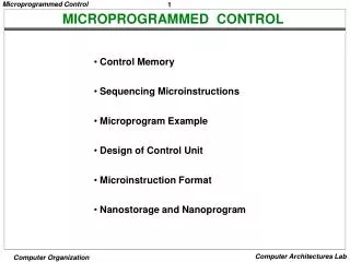
Microprogrammed Control
Chapter11:. Microprogrammed Control. Two methods for generating the control signals are: Hardwired control Sequential logic circuit that generates specific sequences of control signal in response to externally supplied instruction. Microprogrammed control

Microprogrammed Control
E N D
Presentation Transcript
Chapter11: Microprogrammed Control
Two methods for generating the control signals are: • Hardwired control • Sequential logic circuit that generates specific sequences of control signal in response to externally supplied instruction. • Microprogrammed control • A microprogrammed control unit is built around a storage unit is called a control store where all the control signals are stored in a program like format. The control store stores a set of microprograms designed to implement the behavior of the given instruction set.
Term microprogram 1st was coined by M.V.Wilkes in 1950s and then was reviewed by Datamation in February 1964. • Microprogrammed control unit is relatively simple logic circuit that capable of • generating control signals to execute each microinstruction. • sequencing through microoperation
Micro-programmed Control • Use sequences of instructions to control complex operations • Called micro-programming or firmware
Implementation (1) • All the control unit does is generate a set of control signals • Each control signal is on or off • Represent each control signal by a bit • Have a control word for each micro-operation • Have a sequence of control words for each machine code instruction • Add an address to specify the next micro-instruction, depending on conditions
Implementation (2) • Today’s large microprocessor • Many instructions and associated register-level hardware • Many control points to be manipulated • This results in control memory that • Contains a large number of words • co-responding to the number of instructions to be executed • Has a wide word width • Due to the large number of control points to be manipulated
Micro-program Word Length • Based on 3 factors • Maximum number of simultaneous micro-operations supported • The way control information is represented or encoded • The way in which the next micro-instruction address is specified
Micro-instruction Types • Each micro-instruction specifies single (or few) micro-operations to be performed • (vertical micro-programming) • Each micro-instruction specifies many different micro-operations to be performed in parallel • (horizontal micro-programming)
Vertical Micro-programming • Width is narrow • n control signals encoded into log2n bits • Limited ability to express parallelism • Considerable encoding of control information requires external memory word decoder to identify the exact control line being manipulated
Horizontal Micro-programming • Wide memory word • High degree of parallel operations possible • Little encoding of control information
Typical Microinstruction Formats • To execute microinstruction: • turn on all control lines indicated by 1 bit • leave off all control lines indicated by 0 bit • This will cause one / more micro-operations to be performed • If condition indicated by conditions bit false, execute next microinstruction in sequence. • If condition indicated by conditions bit true, next microinstruction to be executed in indicated in address field
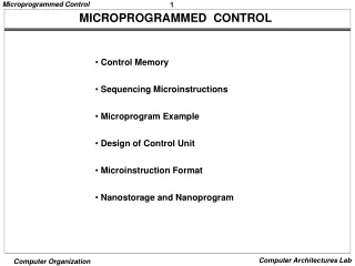
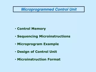
Organization of Control Memory • Arranged in control memory. • Microinstruction in each routine executed sequentially (fetch, indirect, interrupt, execute) and ends with branch/jump • Special execute cycle routines whose only purpose is to signify on of the machine instruction routine (AND, ADD, ..) is to be executed next, depending on current opcode. • Contains a program that describes the behavior of the CU. Implement the CU by simply executing that program.
Functioning of Microprogrammed CU • Sequence login unit issues read command • Word specified in control address register is read into control buffer register • Control buffer register contents generates control signals and next address information • Sequence login loads new address into control buffer register based on next address information from control buffer register and ALU flags
Next Address Decision • Depending on ALU flags and control buffer register • Get next instruction • Add 1 to control address register • Jump to new routine based on jump microinstruction • Load address field of control buffer register into control address register • Jump to machine instruction routine • Load control address register based on opcode in IR
Wilkes Control • 1951 • Matrix partially filled with diodes • During cycle, one row activated • Generates signals where diode present • First part of row generates control • Second generates address for next cycle
Advantages and Disadvantages of Microprogramming • Simplifies design of control unit • Cheaper • Less error-prone • Slower
Tasks Done By Microprogrammed Control Unit • Microinstruction sequencing • Microinstruction execution • Must consider both together
Design Considerations • Size of microinstructions • Address generation time • Determined by instruction register • Once per cycle, after instruction is fetched • Next sequential address • Common in most designed • Branches • Both conditional and unconditional
Sequencing Techniques • Based on current microinstruction, condition flags, contents of IR, control memory address must be generated • Based on format of address information • Two address fields • Single address field • Variable format
Execution • The cycle is the basic event • Each cycle is made up of two events • Fetch • Determined by generation of microinstruction address • Execute • Effect is to generate control signals • Some control points internal to processor • Rest go to external control bus or other interface
A Taxonomy of Microinstructions • Vertical/horizontal • Packed/unpacked • Hard/soft microprogramming • Direct/indirect encoding
Improvements over Wilkes • Wilkes had each bit directly produced a control signal or directly produced one bit of next address • More complex address sequencing schemes, • using fewer microinstruction bits, are possible • Require more complex sequencing logic module • Control word bits can be saved by encoding and subsequently decoding control information
How to Encode • K different internal and external control signals • Wilkes’s: • K bits dedicated • 2K control signals during any instruction cycle • Not all used • Two sources cannot be gated to same destination • Register cannot be source and destination • Only one pattern presented to ALU at a time • Only one pattern presented to external control bus at a time • Require Q < 2K which can be encoded with log2Q < K bits • Not done • As difficult to program as pure decoded (Wilkes) scheme • Requires complex slow control logic module • Compromises • More bits than necessary used • Some combinations that are physically allowable are not possible to encode
Specific Encoding Techniques • Microinstruction organized as set of fields • Each field contains code • Activates one or more control signals • Organize format into independent fields • Field depicts set of actions (pattern of control signals) • Actions from different fields can occur simultaneously • Alternative actions that can be specified by a field are mutually exclusive • Only one action specified for field could occur at a time