The Processor Data Path & Control Chapter 5 Part 3 - Microprogrammed Control Unit
The Processor Data Path & Control Chapter 5 Part 3 - Microprogrammed Control Unit. N. Guydosh 3/1/04+. Tradeoffs. Tradeoffs between hardware vs microprogrammed controller

The Processor Data Path & Control Chapter 5 Part 3 - Microprogrammed Control Unit
E N D
Presentation Transcript
The ProcessorData Path & ControlChapter 5Part 3 - Microprogrammed Control Unit N. Guydosh 3/1/04+
Tradeoffs • Tradeoffs between hardware vs microprogrammed controller • Advantages Of Microprogrammed:Usually Easier To Document And UnderstandMore Flexible: Easier, Faster, And Cheaper To Fix Design bugs • Disadvantages Of Microprogrammed • May Be Slower Than Direct Hardware Implementation • May Involve More Support PeopleTeam Of "Microcoders" & More Managers Needed
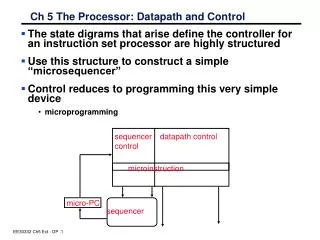
Microprogrammed controller • Control lines directly generated (asserted) by“microinstructions” as they get executed by a data path • Data path for microinstructions is distinct from the data path of the main architecture (MIPS) instructions • An embedded computer within a computer • The microprogrammed controller “computer” is generally special purpose • “micro‑data path”:Typically has only an instruction memory implemented as rom or flash memory rather than a ram has minimal computation capability • Microinstructions: Main goal in life is to generate control signals • orExecute (interpret) architecture instructions
Microprogramms • Two basic categories of microprogramminghorizontal vs vertical (see p. C‑31 ) • Vertical • Shorter word • More decoding needed to interpret fields (maximal encoding) • Words are more functional • Micro data hardware path more complicated • Ex: older IBM main frames (s360/s3670)used it • Horizontal (used here): • Longer word • Direct relationship between fields/word bits and control signals • Minimal encoding of fields ‑ may have a bit significant relationship between word bits and control signals. • Micro data hardware path simpler • Ex:PowerPC’s employed horizontal code
Microinstructions • Relationship to FSM • A state in the FSM usually corresponds to the execution of a microinstruction • Sequencing of microinstructions • Next microinstruction to execute may be sequential, a conditional branch, or an unconditional branch • Flow pattern follows the flow of the state diagram • sequential within a ”routine” • conditional branch based on opcode (and status) to various "subroutines" • unconditional branch usually at the end of a cycle transferring control to the “fetch “ routine • default is sequential • instruction carries a “next address” field. ... Compare to assembly language instructions
Defining The Microinstruction • Microinstruction is made up of a series of fields corresponding each corresponding to related groups of control signals and a sequencing field • Criteria for choosing fields: • must encompass all control signals • Must be consistent don't make "overlapping fields require that a control signal be both asserted de-asserted. • use control signals defined on p. 384, fig. 5.34 for defining fields. ... See also p. 383, fig. 5.33 for big picture … previous slides
Defining The Microinstruction , IRWrite Note: MDR “benignly” written by default Note: IRWrite added above, now 18 control lines.
The Microprogram Number of control lines: 2 1 2 3 4 4 2 ==> 18 total Note “Read PC” includes IRWrite corresponding to fix in Fig. C21.
Dispatch Tables The Microcode assembler uses the encoding of the sequence field in the microword the contents of the above dispatch tables the specification (field ==> control lines) of fig C21 microprogram itself To generate the microinstructions to execute If the sequence field is a dispatch specification selecting one of the tables above, then the opcode is used to access within one of the abovetables.
Implementation 1 1 1 1 1 1 1 2 2 2 1 1 1 The control lines activated are the actual bits of the mico-word selected. … “horizontal microcode” typo see below 2 Note for those with earlier printing of book:BWrite doesn’t seem to get used anywhere. B register is unconditionally written. If BWrite is dropped, we have the correct number control lines (18).